Land Rover Discovery. Manual - part 188


  Index      Land Rover     Land Rover Discovery - service 1995-1996 year


Search            


Content   ..  186  187  188  189   ..


Land Rover Discovery. Manual - part 188


AIR CONDITIONING

1

DESCRIPTION AND OPERATION

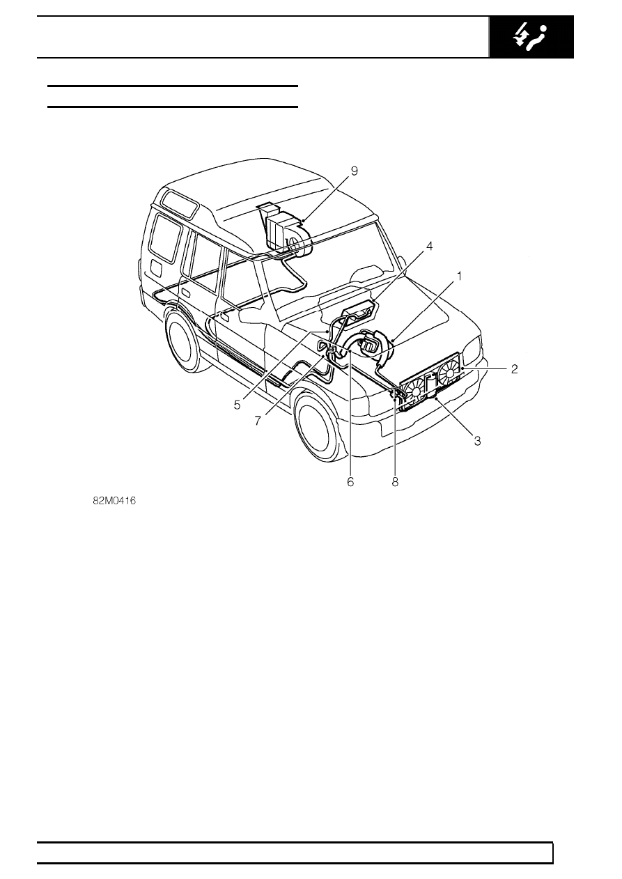
AIR CONDITIONING SYSTEM COMPONENTS

1. Compressor
2. Condenser
3. Receiver/drier
4. Evaporator
5. High pressure servicing connection

6. Low pressure servicing connection
7. Dual pressure switch
8. Sight glass
9. Rear evaporator/blower motor assembly

82

AIR CONDITIONING

2

DESCRIPTION AND OPERATION

SCHEMATIC LAYOUT OF THE AIR CONDITIONING
SYSTEM

1. Compressor
2. Condenser
3. Receiver/drier
4. Thermostatic expansion valve
5. Evaporator
6. Capillary tube
7. Dual pressure switch
8. Cooling fans to maintain air flow
9. Compressor high pressure relief valve

10. Sight glass - refrigerant
11. Drying agent - receiver/drier
12. Blower motor

A1 Ambient air flow through condenser
A2 Ambient air flow through fan and evaporator
A3 Cooled air flow to vehicle interior

F1 High pressure high temperature refrigerant

vapour

F2 High pressure slightly subcooled refrigerant

liquid

F3 High pressure slightly subcooled refrigerant

liquid with moisture, vapour bubbles and foreign
matter removed

F4 Low pressure low temperature mixed liquid and

vapour

F5 Low pressure slightly super heated refrigerant

vapour

AIR CONDITIONING

3

DESCRIPTION AND OPERATION

AIR CONDITIONING SYSTEM OPERATION

The air conditioning system provides the means of
supplying cooled and dehumidified, fresh or
recirculated air to the interior of the vehicle. The
cooling effect is obtained by blowing air through the
matrix of an evaporator unit and when required,
mixing that air with heated air by means of the heater
distribution and blend unit, to provide the conditions
required inside the vehicle. The volume of conditioned
air being supplied is controlled by a variable speed
blower.

A sealed system, charged with Refrigerant R134a,
together with a blower unit, blend unit and control
system combine to achieve the cooled air condition.

For air conditioning air distribution system.

See

HEATING AND VENTILATION, Description and
operation, Heating and ventilation unit

The air conditioning system comprises five major
units:

1. An engine-mounted compressor.
2. A condenser mounted in front of the radiator.
3. A receiver/drier unit located in front of the

condenser.

4. Thermostatic expansion valve mounted above

the evaporator.

5. An evaporator unit mounted in front of the heater

matrix.

NOTE: Vehicles fitted with rear air
conditioning have an additional
evaporator/blower motor assembly located

behind the LH rear compartment lower trim panel.

These units are interconnected by hoses and pipes
carrying Refrigerant R134a, the evaporator is linked
into the vehicle ventilation system.

Refrigeration cycle

1. Compressor

The compressor (1), belt driven from the crankshaft
pulley, pressurises and circulates the refrigerant
through the system. Mounted on the compressor, an
electro-mechanical clutch maintains the correct
temperature and pressure by engaging or disengaging
to support the system’s requirements. The clutch
action is normally controlled by a thermostat located
at the evaporator (5). The compressor is of the
swashplate type having fixed displacement.

Should the temperature at the evaporator (5) fall low
enough for ice to begin to form on the fins, the
thermostat disengages the clutch and also isolates the
cooling fans relays. When the temperature at the
evaporator (5) rises to the control temperature, the
clutch is re-engaged.

Should the system pressure become excessive or
drop sufficiently to cause damage to the compressor
(1) a dual pressure switch (7), located in the high
pressure line, signals the relay unit to disengage the
clutch. The compressor also has an emergency high
pressure relief valve (9) fitted.

The cooling fans are controlled by engine temperature
when the air conditioning is not switched on.

2. Condenser

From the compressor, hot high pressure vaporised
refrigerant (F1) passes to the condenser (2), which is
mounted in front of the engine coolant radiator. Ram
air(A1) passing through the condenser (2),
supplemented by 2 cooling fans (8) mounted in front
of the condenser, cools the refrigerant vapour
sufficiently to form a high pressure slightly subcooled
liquid (F2).

3. Receiver/drier

This liquid then passes to a receiver/drier (3) which
fulfils two functions. It acts as a reservoir and moisture
extractor (11).

A sight glass (10), in the high pressure line, provides a
method of determining the state of the refrigerant
without breaking into the system.

4. Expansion valve

From the receiver/drier (3) the moisture free high
pressure liquid refrigerant (F3) passes through a
thermostatic expansion valve (4). A severe pressure
drop occurs across the valve and as the refrigerant
enters the evaporator space at a temperature of
approximately -5

°

C it boils and vaporises.

82

AIR CONDITIONING

4

DESCRIPTION AND OPERATION

5. Evaporator

As this change of state occurs, a large amount of
latent heat is absorbed. The evaporator is therefore
cooled and as a result heat is extracted from the air
flowing across the evaporator. The air flow is
controlled by the ventilation fan which can be
operated at anyone of four speeds.

To prevent liquid passing through to the compressor,
a capillary tube (6), attached to the outlet pipe of the
evaporator (5) and connected to the thermostatic
expansion valve (4), controls the amount that the
valve opens and closes in relation to the temperature
of the low pressure high temperature refrigerant
vapour (F4) at the outlet. The atomised refrigerant
then passes through the evaporator (5). Fan blown air
(A2) passes through the matrix (A3) of the evaporator
and is cooled by absorption due to the low
temperature refrigerant passing through the
evaporator.

A thermostat is fitted in the airflow out of the
evaporator to sense the temperature of the exterior
fins. Should ice begin to form, due to a too cold
condition, it will signal to disengage the
electro-mechanical clutch on the compressor (1).

From the evaporator, low pressure slightly
superheated refrigerant (F5) passes to the
compressor to complete the cycle.

AIR CONDITIONING CONTROL SYSTEM

The air conditioning control system comprises relays,
thermostat, pressure switches, and a control panel.
Inputs from outside the air conditioning system
comprise temperature information from the engine
cooling system. Together these controls, in
conjunction with the cooling fans, compressor clutch,
blower and heater distribution and blend unit enable
minimal input to maintain the required environment
inside the vehicle.

When air conditioning is not selected, air is supplied
by ram effect or blower to the areas selected by the
controls. The air mix flap on the blend unit controls the
temperature of the air being supplied. No cooled air is
available.

Selecting air conditioning provides the added facility of
cooled air available to be mixed as before. When
required a fully cold condition can be selected by
turning the temperature controls to cold, which
automatically closes the heated coolant access to the
heater matrix. Mixtures of cooled, fresh, and hot air
can be selected to give required interior environmental
conditions by selection at the control panel.

Dual pressure switch
This switch, located in the high pressure line between
the receiver drier and the expansion valve, monitors
refrigerant pressure and by means of the relay module
controls the following system functions:

1. Refrigerant pressure drops below 2.0 bar, 29

lbf/in

2

(due to possible leakage), the

compressor’s electro-mechanical clutch is
dis-engaged.
When pressure rises above 2.0 bar, 29 lbf/in

2

the

compressor’s clutch is re-engaged.

2. Refrigerant pressure rises above 32 bar, 455

lbf/in

2

(due to possible blockage), even with

cooling fan operation, the compressor’s
electro-mechanical clutch is dis-engaged.
When the pressure drops below 26 bar, 375
lbf/in

2

the compressor clutch is re-engaged.


Content   ..  186  187  188  189   ..