Land Rover Discovery. Manual - part 115


  Index      Land Rover     Land Rover Discovery - service 1995-1996 year


Search            


Content   ..  113  114  115  116   ..


Land Rover Discovery. Manual - part 115


44

AUTOMATIC GEARBOX

22

REPAIR

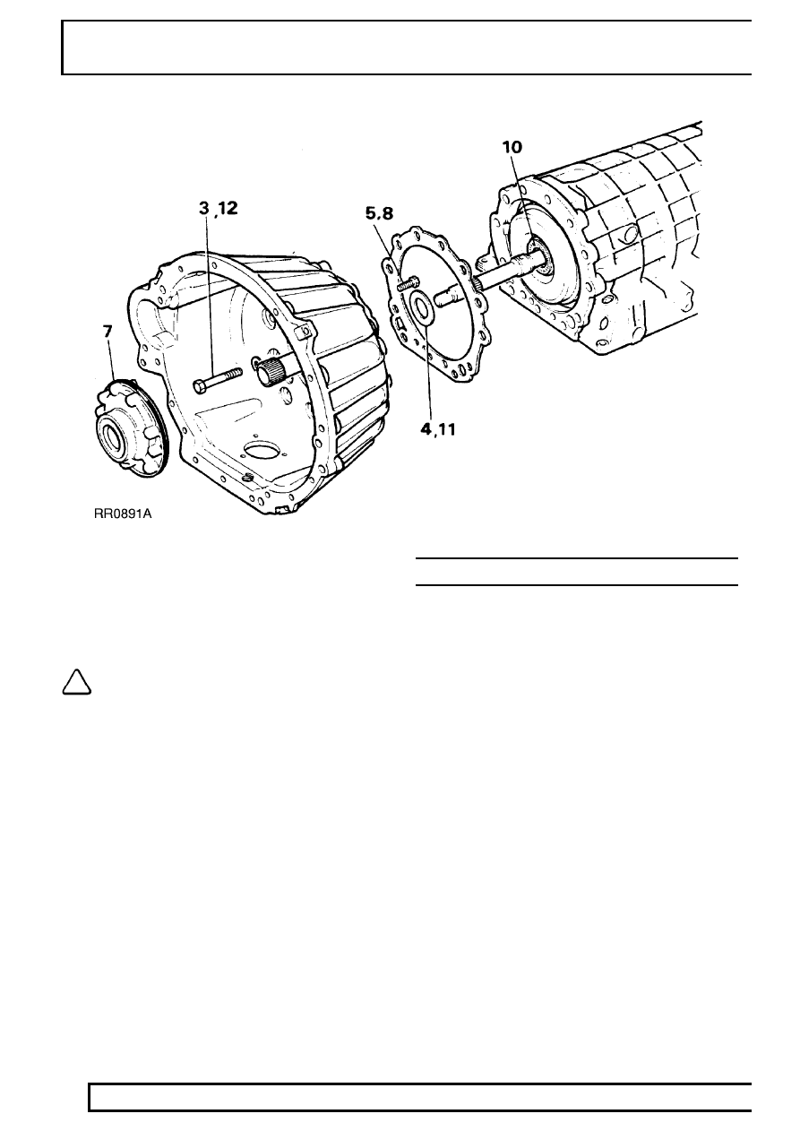
13. Place end-float gauge LST111 onto pump

housing and check that axial play is between
0.2-0.4 mm. Replace existing washer, situated at
rear of intermediate plate, with suitable washer
to give required end-float.

NOTE: If damage is apparent to bolts they
should be replaced.

14. Refit torque converter into housing using torque

converter handles 18G1501. Check dimension
converter fixing boss to converter housing face is
50 mm. This shows converter is properly seated
in housing.

15. Refit gearbox/transfer box assembly.

See

LT230T Transfer Gearbox

GEAR SELECTOR-INTERLOCK

For remove and refit of gear selector interlock.

See

ELECTRICAL, Repair, Gear Selector-Interlock

ZF

1

SPECIFICATIONS, TORQUE

TORQUE VALUES

NOTE: Torque wrenches should be regularly checked for accuracy to ensure that all fixings are
tightened to the correct torque.

Nm

Coupling shaft to mainshaft

42*

......................................................................

Filler tube to sump

68

.....................................................................................

Gear change lever to gearbox

25

...................................................................

Cooler pipe adaptor to gearbox

42

.................................................................

Securing screws - clutch F

10

.........................................................................

Securing screw - parking pawl

10

...................................................................

Securing screws - pump

10

............................................................................

Intermediate plate plugs (M20)

50

..................................................................

Intermediate plate plugs (M14)

40

..................................................................

Bell housing mounting bolts

46

.......................................................................

Governor mounting screws

10

........................................................................

Extension housing bolts

23

.............................................................................

Control unit mounting bolts

8

.........................................................................

Sump plug

10

..................................................................................................

Mounting screws for sump

8

..........................................................................

Drive plate to converter

39*

.............................................................................

Gearbox to engine

42

.....................................................................................

Strut (threaded end)

42

...................................................................................

Bottom cover to converter housing

9

.............................................................

Cover - converter housing

9

...........................................................................

Drive plates to crankshaft adaptor

40*

............................................................

Adaptor to crankshaft

84

.................................................................................

NOTE: * These bolts must have threads coated with Loctite 270 prior to assembly.

Torque values below are for all screws and bolts used except for those that are specified otherwise.

METRIC

Nm

M5

6

......................................................................................................

M6

9

......................................................................................................

M8

25

.....................................................................................................

M10

45

...................................................................................................

M12

90

...................................................................................................

M14

105

..................................................................................................

M16

180

..................................................................................................

UNC / UNF

1/4

9

......................................................................................................

5/16

24

...................................................................................................

3/8

39

.....................................................................................................

7/16

78

...................................................................................................

1/2

90

.....................................................................................................

5/8

136

....................................................................................................

44

AUTOMATIC GEARBOX

2

SPECIFICATIONS, TORQUE

ZF GEARBOX DATA

Axial end float 0.2 to 0.4 mm.

From torque converter boss to torque converter
housing face 50 mm

Freewheel cage assembly to ring gear; minimum
clearance 0.1 mm

Output shaft above cylinder F assembly; dimension
10.00 mm

A cylinder protrusion above gearbox front face not
more than 8.5 mm

ZF

1

SERVICE TOOLS

AUTOMATIC GEARBOX HOLDING FIXTURE

NOTE: This fixture enables ZF gearbox to be held securely during bench sited repairs. It can be
manufactured to details given, or purchased under service tool number LST 118.


Content   ..  113  114  115  116   ..