Land Rover Discovery. Manual - part 96


  Index      Land Rover     Land Rover Discovery - service 1995-1996 year


Search            


Content   ..  94  95  96  97   ..


Land Rover Discovery. Manual - part 96


MANIFOLD AND EXHAUST SYSTEM

7

REPAIR

Refit

19. Ensure mating faces of inlet manifold and

cylinder head are clean.

20. Fit a new gasket, position inlet manifold to

cylinder head.

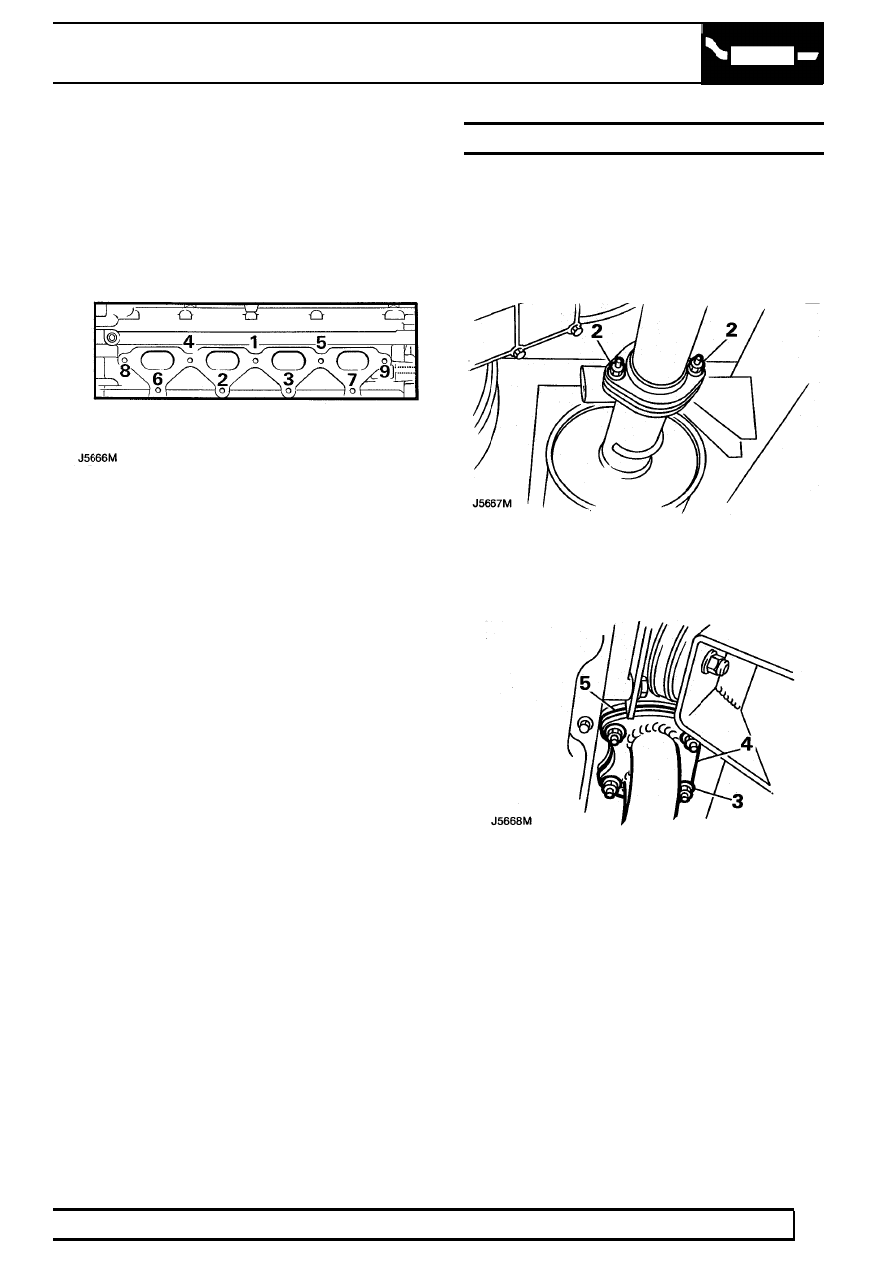
21. Fit nuts and bolts, tighten in the order shown to

the correct torque

25Nm

22. Position engine breather hose to manifold and

secure with bolts.

23. Connect fuel injector harness and intake air

temperature sensor multiplug.

24. Connect fuel hose to pressure regulator and

secure with clip.

25. Fit fuel pipe to fuel rail, tighten union to

10Nm

26. Connect vacuum hoses to manifold.
27. Position engine harness and cam cover brackets

to manifold, secure with bolts.

28. Connect breather hose and brake servo hose to

manifold, secure with clips.

29. Connect multiplug to fuel temperature sensor.
30. Connect breather hose to throttle housing and

secure with clip.

31. Connect throttle cable to cam and secure to

abutment bracket.

32. Connect coolant bypass hose to throttle housing.
33. Connect stepper motor and throttle

potentiometer multiplugs.

34. Connect air cleaner hose to throttle housing and

secure with clip.

35. Connect battery negative lead.
36. Adjust throttle cable.

EXHAUST MANIFOLD GASKET - Mpi

Service repair no - 30.15.12

Remove

1. Raise vehicle.
2. Loosen 2 nuts securing downpipe to silencer

box.

3. Remove 4 nuts securing downpipe to exhaust

manifold.

4. Release downpipe from exhaust manifold.
5. Discard gasket.

30

MANIFOLD AND EXHAUST SYSTEM

8

REPAIR

6. Disconnect oxygen sensor multiplug.
7. Release multiplug from bracket on thermostat

housing.

8. Release harness from cable tie.

9. Remove drive belt.

10. Remove 2 front bolts securing generator to

mounting bracket.

11. Remove 2 rear bolts securing generator to

mounting bracket.

12. Move generator from mounting bracket and

place aside.

13. Remove exhaust manifold heat shield.
14. Remove dipstick and bolt securing dipstick tube

to coolant rail.

15. Remove dipstick tube from cylinder block.

16. Remove 3 bolts and 2 nuts securing exhaust

manifold to cylinder head.

17. Release coolant rail bracket from manifold studs.
18. Remove exhaust manifold and discard gasket.

Refit

NOTE: For torque values.

See

Specifications, torque, Torque Values

19. Clean mating faces of exhaust manifold and

cylinder head.

20. Fit new manifold gasket and align exhaust

manifold to cylinder head.

21. Position coolant rail bracket to manifold studs.
22. Fit manifold nuts and bolts, tighten to the correct

torque in the order shown.

23. Secure oxygen sensor multiplug to bracket.
24. Connect oxygen sensor multiplug.
25. Fit new manifold flange gasket and align exhaust

front pipe to manifold.

26. Fit nuts and tighten diagonally to the correct

torque.

27. Tighten exhaust downpipe to silencer box nuts

to the correct torque.

28. Position generator to mounting bracket.
29. Fit and tighten 4 generator securing bolts.
30. Refit drive belt.

MANIFOLD AND EXHAUST SYSTEM

9

REPAIR

MANIFOLD CHAMBER GASKET - Mpi

Service repair no - 30.15.37

Remove

1. Disconnect battery negative lead.
2. Position absorbent cloth around fuel pipe to fuel

rail union. Loosen union to relieve pressure.
Re-tighten union.

3. Release clip and remove air cleaner to throttle

housing hose.

4. Disconnect stepper motor and throttle

potentiometer multiplugs.

5. Release clip and disconnect breather hose from

throttle housing.

6. Release throttle cable from abutment bracket.
7. Release throttle cable from cam. Remove

coolant bypass hose from throttle housing.

8. Disconnect fuel temperature sensor multiplug.
9. Release clip and disconnect brake servo hose

from manifold.

30

MANIFOLD AND EXHAUST SYSTEM

10

REPAIR

10. Release clip and disconnect breather hose from

manifold.

11. Release 2 bolts securing camshaft cover

brackets to manifold.

12. Disconnect 4 vacuum hoses from manifold.
13. Remove 6 bolts securing manifold chamber to

lower manifold.

14. Remove manifold chamber and collect gaskets.

Refit

NOTE: For torque values.

See

Specifications, torque, Torque Values

15. Ensure mating faces of manifold chamber and

lower manifold are clean.

16. Fit a new gasket, position manifold chamber to

lower manifold.

17. Fit bolts, tighten to the correct torque.
18. Connect vacuum hoses to manifold.
19. Position camshaft cover brackets to manifold,

secure with bolts.

20. Connect breather hose and brake servo hose to

manifold, secure with clips.

21. Connect multiplug to fuel temperature sensor.
22. Connect breather hose to throttle housing and

secure with clip.

23. Connect throttle cable to cam and secure to

abutment bracket.

24. Connect coolant bypass hose to throttle housing.
25. Connect stepper motor and throttle

potentiometer multiplugs.

26. Connect air cleaner hose to throttle housing and

secure with clip.

27. Reconnect battery negative lead.
28. Adjust throttle cable.


Content   ..  94  95  96  97   ..