Land Rover Discovery. Manual - part 28
V8i
3
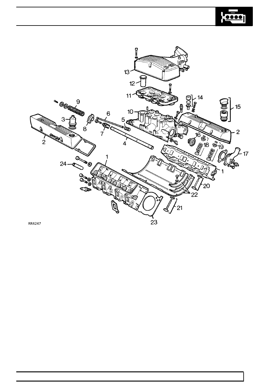
DESCRIPTION AND OPERATION
1. Cylinder heads (2)
2. Rocker covers (2)
3. PCV filter
4. Rocker shafts (2)
5. Hydraulic tappets (8)
6. Pushrods (8)
7. Rocker brackets (8)
8. Rocker arms (4) left and (4) right
9. Rocker shaft springs (6)
10. Inlet manifold
11. Plenum chamber lower
12. Ram pipes (8)
13. Plenum chamber upper
14. PCV air intake filter
15. Oil filler
16. Thermostat
17. Thermostat cover
18. Inlet valve seal, spring, cap and collets (8)
19. Exhaust valve seal, spring, cap and collets (8)
20. Inlet valve and seat (8)
21. Exhaust valve and seat (8)
22. Inlet manifold gasket and seals
23. Cylinder head gaskets (2)
24. Valve guides (16)