Defender 300Tdi (1996+). Manual - part 43


  Index      Land Rover     Defender 300Tdi - service repair manual 1996 year


Search            


Content   ..  41  42  43  44   ..


Defender 300Tdi (1996+). Manual - part 43


PROPELLER SHAFTS

1

DESCRIPTION AND OPERATION

PROPELLER SHAFT

Description

The front and rear propeller shafts have non-constant
velocity type universal joints, with needle roller
bearings. The bearing cups are pre-packed with
lubricant on assembly and a grease nipple is fitted for
servicing as specified, in maintenance section.

Both shafts have Rilsan coated sliding splines to
accommodate the variation in distance between the
axles and transmission. The splines are pre-packed
with lubricant and protected by a rubber gaiter. A
grease nipple is also fitted for servicing requirements.

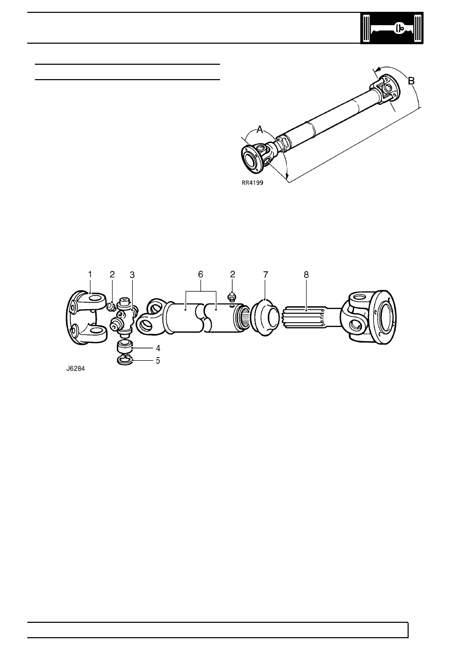
The front shaft which is shorter than the rear is
’phased’, with the joints at each end, A and B
mis-aligned as shown.

The phasing is necessary on the front shaft only to
allow for greater variation in angular changes.

Propeller shaft

1. Flanged yoke
2. Grease nipple
3. Journal spider
4. Needle roller bearing
5. Circlip
6. Splined shaft
7. Rubber gaiter (dust cap)
8. Splined shaft

PROPELLER SHAFTS

1

FAULT DIAGNOSIS

VIBRATION HARSHNESS

Check that the propeller shaft universal joints and
sliding splines are not siezed or worn and that the
shafts are correctly aligned.

NOTE: In the event that both shafts are
satisfactory, but the vibration/harshness is
still present, the transfer box operation

and balance of the road wheels should be
checked.

For transfer box operation

See TRANSFER

GEARBOX, Fault diagnosis, Transfer Gearbox -
Oil seal locations 
.

For balance of road wheels

See WHEELS AND

TYRES, Repair, Wheel Balancing.

PROPELLER SHAFTS

1

REPAIR

PROPELLER SHAFT

Service repair no - 47.15.02/03

Remove

1. Place vehicle on ramp.

2. Mark drive flanges at each end of propeller shaft

for reassembly.

3. Remove 4 bolts/nuts from each end and remove

propeller shaft.

NOTE: A chassis undertray may be fitted
on some vehicle derivatives to conform to
legal requirements. When under chassis

remove and refit procedures are required, it may
be necessary to remove the undertray

See

CHASSIS AND BODY, Repair, Front undertray or
See CHASSIS AND BODY, Repair, Rear undertray
.

Service repair no - 47.15.11/12

Overhaul

4. Thoroughly examine universal joint for signs of

damage or wear. Replace if necessary.

5. Clean universal joint bearing cups and circlips.

CAUTION: To ensure correct assembly
and reduce possibility of imbalance, mark
position of spider pin lubricator relative to

journal yoke ears, before removing propeller shaft
joint.

6. Remove circlips, and grease nipple.
7. Tap yokes to eject bearing cups.
8. Remove bearing cups and spider.
9. Repeat instructions 4 to 7 for opposite end of

propeller shaft if necessary.

10. Clean yokes and bearing cup locations.

47

PROPELLER SHAFTS

2

REPAIR

Assembly

11. Remove bearing cups from new spider.
12. Check all needle rollers are present and

positioned in bearing cups.

13. Ensure bearing cups are one-third full of

lubricant

See LUBRICANTS, FLUIDS AND

CAPACITIES, Information, Recommended
lubricants and fluids 
.

14. Enter new spider with seals into yokes of sliding

member flange.

15. Partially insert one bearing cup into flange yoke

and enter spider trunnion into bearing cup.

16. Insert opposite bearing cup into flange yoke.
17. Press both cups into place.

18. Press each cup into its respective yoke up to

lower land of circlip grooves. Damage may be
caused to cups and seals if cups pass this point.

19. Fit circlips and check no end float exists.

20. Engage spider in yokes of sliding member. Fit

bearing cups and circlips as described in
instructions 14 to 19.

21. Fit grease nipples to spider and sliding member.
22. Apply instructions 14 to 19 to opposite end of

propeller shaft.

23. Fit grease nipple and lubricate.

Refit

24. Fit propeller shafts to vehicle with sliding joints to

transfer box and tighten nuts to

47 Nm (35

lbf/ft).


Content   ..  41  42  43  44   ..