Defender 90 / 110 / 130. Manual - part 157
..
.
:
...
...
.
.
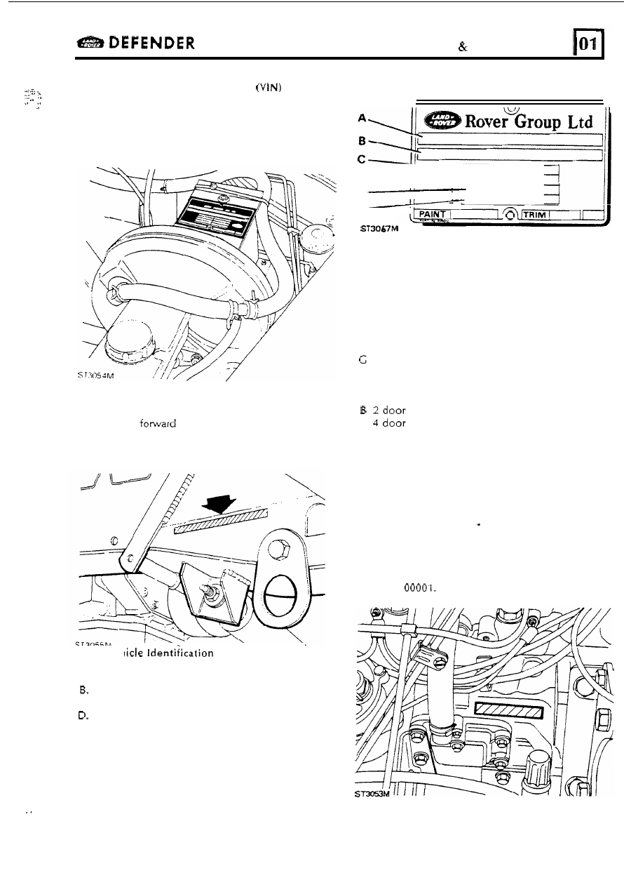
LOCATION
OF VEHICLE IDENTIFICATION
UNIT NUMBERS
VEHICLE IDENTIFICATION NUMBER
The Vehicle Identification Number and the
recommended maximum vehicle weights are
stamped o n a plate riveted t o the top
of the pedal
box behind the brake servo
The number
is
also stamped on the right-hand
side
of the chassis
of
the spring mounting turret.
Always quote this number when writing t o Land
Rover.
Key to Veh
\
Number Plate
A.
Type approval
VIN
(minimum
of
17
digits)
C. Maximum permitted laden weight
for
vehicle
Maximum vehicle and trailer weight
E.
Maximum road weight
-
front axle
F.
Maximum road weight
-
rear axle
E
F
PAINT
TRIM
The Vehicle Identification Number identifies the
manufacturer, model range, wheel
base,
body type,
engine, steering, transmission, model name and
place
of manufacture. The following example shows
the coding process.
SAL World manufacturer identifier
LD Land Rover
Class
100
inch
V
Class
90
inch
H
Class
110
inch
A
Basic
M
H High Capacity
F
Tdi o r
8
5 speed LHD o r
7
5 speed RHD
H
1991
MY
A
Solihull site
ENGINE SERIAL NUMBER Tdi ENGINE
The engine number
is stamped o n the cylinder
block o n the right hand side
of the engine above
the camshaft front cover plate. Commencing Serial
Number
IIL
7