Defender 90 / 110 / 130. Manual - part 129
AIR
CONDITIONING- L.H.
R
.
H
.
STEERING
.
NOTE: A special wrench should be used to adjust the
valve to prevent damage to the stem.
The stem type service valve has three positions, the
operation
of which is explained as follows.
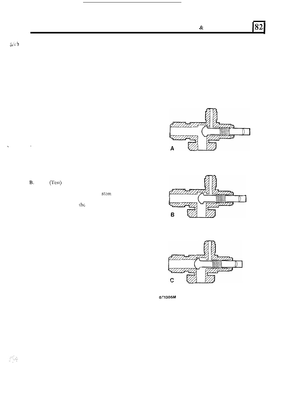
A.
ON: FULLY ANTICLOCKWISE
-
Normal
operating position, and the position which is used
for connecting and disconnecting the manifold
gauge set, is t h e
on position. The stem is turned
fully anticlockwise. This seals the service gauge
port from receiving any refrigerant flow.
MID
POSITION
-
After the service gauge
manifold has been installed (the valve stem is
in the
on position), turn the valve
the required
number of turns clockwise. This will put the valve
stem seat midway in
service valve and allow full
system operation while permitting refrigerant
pressure to reach the gauges.
C. OFF: FULLY CLOCKWISE
-
With
t h e
service
valve stem turned fully clockwise, the valve
will
block passage
of
refrigerant flow through the
system. As illustrated, the refrigerant flow to or
from the compressor (depending
on whether it is
high side or low
side)
is blocked.
WARNING:
NEVER operate the air conditioning
system with the service valves in the
OFF POSITION, it
will cause severe damage to the compressor.
3