Defender 90 / 110 / 130. Manual - part 88
LT85 FIVE SPEED GEARBOX
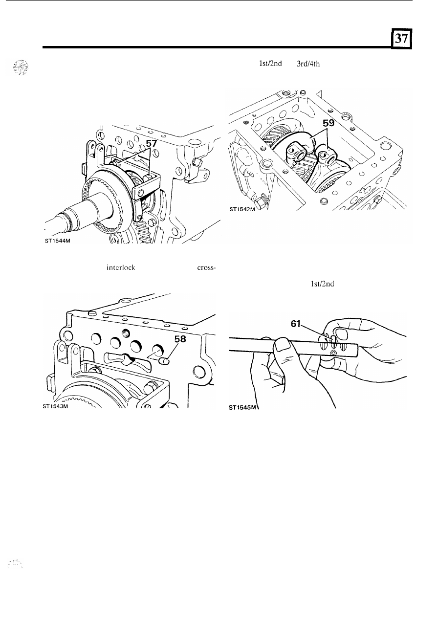
Selector rails
and forks
56. Locate 5th gear fork and bracket
on
to synchro hub
57. Secure fork bracket to gearbox with two bolts,
and gcarbox dowels.
plain washers
and
spring washers.
.
59.
Fit
and
selector forks.
58. Fit selector
rail
plungers into t h e
drilling in the gcarbox case.
60. Fit reverse cross-over lever.
61. Insert interlock into
selector rail.
81