Defender 90 / 110 / 130. Manual - part 2


  Index      Land Rover     Defender 90 / 110 / 130 - service repair manual


Search            


Content   ..  1  2  3   ..


Defender 90 / 110 / 130. Manual - part 2


LOCATION 

OF VEHICLE IDENTIFICATION AND UNIT NUMBERS 

FRONT AXLE 

Stamped on top 

of the left-hand axle tube. 

REAR AXLE 

Stamped on rear 

of 

left-hand axle tube. 

MAIN GEARBOX LT77 

4 CYLINDER VEHICLES 

Stamped on a pad on the right-hand side of the gearbox 
immediately below the 

oil filler level plug. 
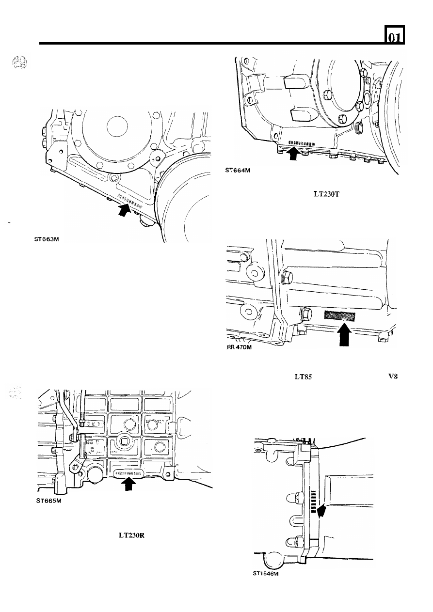
TRANSFER  GEARBOX 

4  CYLINDER 

VEHICLES 

Stamped  on  the  casing  on  the  left-hand  side  of  the 
gearbox  below  the  mainshaft  rear  bearing  housing 
adjacent to the bottom cover. 

TRANSFER  GEARBOX 

4  CYLINDER 

AND  V8  VEHICLES  FROM  SERIAL  NUMBER 
SUFFIX 

‘B’ ONWARD 

MAIN  GEARBOX 

FIVE  SPEED 

VEHICLES 

Stamped  on  the  right-hand  side 

of  the  front  bearing 

plate. 

G

EN

ERA

SPECIFICATION DATA 

ENGINE 
Type 

................................................................. 

Number 

of  cylinders 

............................................. 

Bore 

................................................................. 

Stroke 

............................................................... 

Capacity 

............................................................ 

Valve operation.. 

................................................. 

Maximum power-  

..................................... 

Maximum power 

KW.. 

...................................... 

Maximum torque 

................................................. 

Eight, two banks 

of  four 

(3.500 in) 
(2.800 in) 

3528 

(215 

Overhead by push-rod 

at 

84.6 

251 

(185 

lb ft) at 2500 

Crankshaft 

Main journal diameter 

....................................... 

Minimum regrind diameter 

.............................. 

Crankpin journal diameter. 

Minimum regrind diameter 

.............................. 

Crankshaft end thrust 

........................................ 

Crankshaft end-float 

.......................................... 

58,409 

58,422 

(2.2996 

2.3001 

in) 

57,393 

57,406 

(2.2596 

2.2601 

in) 

50,800 

50,812 

(2.0000 

2.0005 

in) 

49,784 

49,797 

1.9605 in) 

Taken 

on 

thrust washers 

of centre main bearing 

(0.004 

0.008 

in) 

................................. 

Main bearings 

Number and type 

.............................................. 

5 ,  

Vandervell shells 

0,010 

0,048 

(0.0004 

0.0019 in) 

0,254 

0,508 

(0.010 in, 0.020 in) 

Material 

......................................................... 

Lead-indium 

Diametrical clearance 

........................................ 

Undersizes 

...................................................... 

Connecting rods 

Type.. 

............................................................ 

Horizontally split big end, 

small end 

Length between centres 

...................................... 

(5.662 

5.658 

in) 

Big end bearings 

Type and material 

............................................. 

Diametrical clearance 

....................................... 

0,015 

(0.0006 

in) 

End-float on crankpin 

....................................... 

(0.006  0.014 in) 

Undersizes 

...................................................... 

Vandervell 

VP lead-indium 

0,254 

0,508 

(0.010 

in, 

0.020 in) 

Gudgeon pins 

Length 

........................................................... 

(2.861 

in) 

Fit-in connecting rod 

......................................... 

Clearance 

in piston 

............................................ 

0,002 

0,007 

(0.0001 

0.0003 in) 

Diameter 

........................................................ 

22,215 

(0.8746 

0.8749 in) 

Press fit 

Pistons 

Clearance in 

bore 

at 

at 

right angles to gudgeon pin 

.................................. 

0,018 

0,033 

in) 

GENERAL SPECIFICATION DATA 

Piston rings 

Number of  compression 

..................................... 

Number of  oil 

.................................................. 

No. 

compression ring 

....................................... 

No. 2 compression ring.. 

..................................... 

Width 

of 

compression rings 

................................. 

Compression ring gap 

........................................ 

Oil ring type 

.................................................... 

Oil ring gap 

..................................................... 

Oil ring width. 

.................................................. 


Chrome parallel faced 

Stepped to 

'L' 

shape and marked 

'T' or 

'TOP' 

(0.0615 

0.0625 in) 

(0.017 

0.022 in) 

Perfect circle, type 98-6 
4,811 

(0.1894 in) max 

(0.015 

0.055 in) 

Camshaft 

Location 

......................................................... 

Central 

Bearings 

......................................................... 

Non-serviceable 

Number of  bearings 

........................................... 

Drive 

............................................................. 

Chain 

(0.375 

in) pitch 

Valves 

Inlet 

........................................................... 

Exhaust.. 

..................................................... 

Inlet 

........................................................... 

Exhaust.. 

..................................................... 

Inlet 

........................................................... 

Exhaust.. 

..................................................... 

inlet 

........................................................... 

Exhaust 

....................................................... 

Inlet 

........................................................... 

Exhaust 

....................................................... 

Valve lift (inlet and exhaust). 

............................... 

Valve spring length fitted 

.................................... 

Seat angle: 

Head diameter: 

Stem diameter: 

Stem t o  guide clearance: 

...... 

(4.590 

4.620 in) 

(4.590 

4.620 in) 

(1.565 

1.575 in) 

34,226 

34,480 

(1.3475 

1.3575 in) 

8,664 

8,679 

(0.3411 

0.3417 in) 

8,651 

8,666 

(0.3406 

0.3412 in) 

0,025 

0,066 

(0.0010 

0.0026 in) 

0,038 

0,078 

(0.0015 

0.0031 in) 

(0.374 in) 
(1.590 in) at pressure of 

(65 lbs) 

Lubrication 

System 

........................................................... 

System pressure, engine warm at 2400 

............. 

Wet sump, pressure fed 

2,8 kgf 

(30 

40 Ibf 

Oil filter (external). 

........................................... 

Full-flow, self-contained cartridge 

Oil filter (internal) 

............................................ 

Gauze. Pump intake filter 

Oii pump type 

.................................................. 

Gear 

Oil pressure 

valve 

Type 

.............................................................. 

Non-adjustable 

Relief valve spring: 

Free length 

................................................... 

Compressed length at 4,2 

(9.3 lb) load 

............ 

in) 

(1.800 in) 

Oil filter by-pass valve 

Type 

............................................................... 

Non-adjustable 

By-pass valve spring: 

Free length 

................................................... 

(1.48 in) 

Compressed length at 

(0.75 

lb). 

............... 

(0.89 in) 

GENERAL SPECIFICATION 

DATA 

2.25 

LITRE 

PETROL ENGINE 

’. 

ENGINE 

Bore 

................................................................. 

Stroke 

............................................................... 

Type 

................................................................. 

Capacity 

............................................................ 

Valve operation. 

.................................................. 

Compression ratio.. 

.............................................. 

Maximum power 

4000 

................................. 

Maximum torque 

2000 rpm.. 

............................... 

cylinder 

(3.562 in) 

(3.500 in) 

2286 

(139.500 

Overhead by push-rod 
8.0: 1 
55.2 Kw  (74 bhp) 
163 

(120 Ibf ft) 

Crankshaft 

Main journal diameter 

....................................... 

63,487 

63.500 

(2.4995 

2.500 in) 

Minimum regrind diameter 

.............................. 

63,246 

63,2333 

(2.4900 

2.4895 in) 

Crankpin 

diameter 

.................................. 

58,725 

58,744 

(2.312 

2.31275 in) 

Minimum regrind diameter 

.............................. 

58,48985 

58,47080 

(2.30275 

2.30200 in) 

Taken on thrust washers at centre main bearing 

Crankshaft end-float 

.......................................... 

(0.002 

0.006 in) 

Crankshaft end thrust 

........................................ 

Main bearings 

Number and type 

.............................................. 

Material 

......................................................... 

Diametrical clearance 

........................................ 

Undersizes 

...................................................... 

halved shells 

Steel shell, tin-aluminium lined 
0,020 

0,063 

(0.0008 

0.0025 in) 

(0.010 in) 

Connecting rods 

Type 

.............................................................. 

Horizontally split big end, plain small end 

Length between centres.. 

.................................... 

(6.904 

6.908 in) 

Big end bearings 

Type and material 

............................................. 

Steel shell, copper-lead lined 

0,019 

0,068 

0.0027 in) 

Diametrical clearance 

........................................ 

End-float on crankpin 

........................................ 

. . . . .  

(0.007 

0.012 in) 

. . . . .  

Undersizes 

...................................................... 

(0.010 in) 

Gudgeon pins 

Type 

.............................................................. 

Floating 

Fit in piston 

..................................................... 

Push 

fit by hand 

Clearance in connecting rod 

................................ 

0,007 

0,015 

(0.0003 

0.0006 in) 

Pistons 

Type 

compression ratio 

............................... 

Aluminium alloy, flat top 

Clearance in bore, measured at bottom of  skirt at 
right angles to gudgeon pin: 

Standard size pistons 

...................................... 

(0.0023 

0.0027 in) 

Oversize pistons 

............................................ 

0,043 

0,055 

(0 

in) 


Content   ..  1  2  3   ..