Defender (1993+). Manual - part 32
FUEL SYSTEM
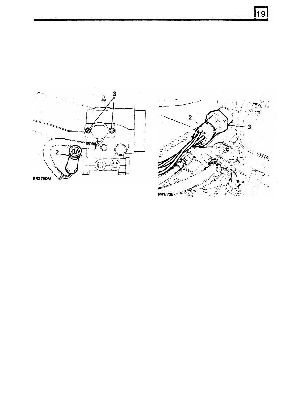
REMOVING
THROTTLE
POSITION SENSOR
To Remove
To Remove
REMOVING IDLE AIR CONTROL VALVE
1.
Disconnect battery ground terminal.
1.
Disconnect battery ground terminal.
2.
Disconnect electrical plug.
2. Remove multi-plug.
3.
Remove
two
screws securing throttle position
3.
Unscrew idle air control valve from rear
sensor to plenum chamber and carefully pull
plenum chamber.
throttle position sensor
off throttle shaft.
4.
Remove washer.
4.
Remove old gasket.
To Refit
5.
Fit new gasket.
6.
Align throttle position sensor and shaft fiats,
slide switch
on
to
throttle shaft. Secure throttle
position sensor to plenum chamber.
To Refit
5. Fit
NEW sealing washer.
CAUTION: D O NOT operate throttle mechanism
while throttle position sensor is loosely fitted,
NOTE: If same idle air control valve is being
damage may be caused to throttle position
refitted clean sealing compounds from threads.
sensor wiper track.
Apply Loctite 241 to threads of idle air control
valve before reassembly.
6. Tighten idle air control valve to 20 Nm.
7. Reverse removal instructions.
REISSUED:
FEB
1993
9