Defender Electric Diagrams. Manual - part 11


  Index      Land Rover     Land Rover Defender Electric Diagrams - manual 1997 year


Search            


Content   ..  9  10  11  12   ..


Defender Electric Diagrams. Manual - part 11


FUSE DETAILS

DEFENDER 90 NAS

REV: 9/97

1

INTRODUCTION

The following tables give details of power supply through the engine and passenger
compartment fuse boxes.

Note: Some fuse numbers may be followed by a letter, either an ‘E’ or a ‘P’. ‘E’ denotes

a fuse located in the engine compartment fuse box, and ‘P’ a fuse located in the
passenger compartment fuse box.

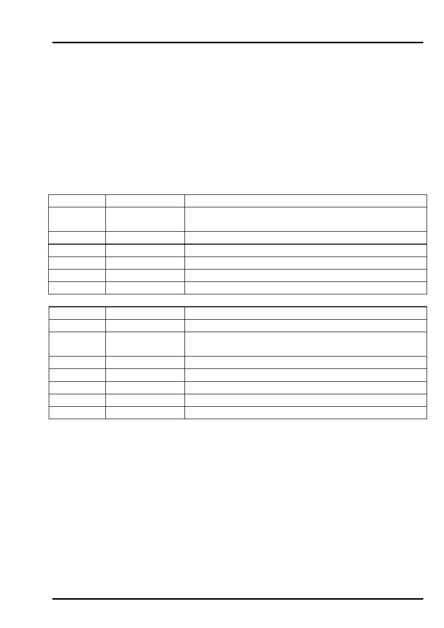
Engine Compartment Fuse Box

Link

Rating

Function

1

100 Amp

Link 3, Link 4, Link 5, Link 6, Fuse 1 (E), Fuse 2 (E), &
Fuse 3 (E).

2

60 Amp

Fuse 13 (P), Fuse 14 (P), Fuse 15 (P), & Fuse 16 (P).

3

60 Amp

Lighting switch.

4

30 Amp

Lighting switch.

5

60 Amp

Fuse 2 (P), Fuse 3 (P), Ignition switch, & Starter relay.

6

30 Amp

Heater rear screen relay.

Fuse

Rating

Function

1

30 Amp

Interior Lamp Unit.

2

20 Amp

Column switch, Multi-function ECU, Interior lamp -
front, Analogue clock, Key-in sensor.

3

30 Amp

Engine immobilisation ECU.

4

10 Amp

Not used.

5

30 Amp

Hazard warning switch.

6

15 Amp

Engine management relay module.

7

20 Amp

Engine management relay module.

FUSE DETAILS

2

DEFENDER 90 NAS

REV: 9/97

Passenger Compartment Fuse Box

Fuse

Rating

Function

1

15 Amp

Instrument pack, Multi-function ECU, Headlamp relay,
Interior lamp - rear, & Warning light check unit.

2

10 Amp

Radio cassette player.

3

5 Amp

Diagnostic socket.

4

15 Amp

Blower motor - front.

5

7.5 Amp

Radio cassette player.

6

15 Amp

Radio cassette player.

7

7.5 Amp

Headlamp - RH.

8

7.5 Amp

Headlamp - LH.

9

7.5 Amp

Headlamp - RH.

10

7.5 Amp

Headlamp - LH.

11

5 Amp

In-line resistor, Front side lamp - LH, Front side
repeater - LH, Trailer pick-up, Rear number plate lamp -
LH, Tail lamp - LH, Rear side marker lamp - LH,
Illumination relay, Instrument illumination dimmer, &
Radio cassette player.

12

5 Amp

Front side lamp - RH, Front side marker lamp - RH,
Rear side marker lamp - RH, Tail lamp - RH, Trailer
pick-up, & Instrument pack.

13

20 Amp

Not used.

14

20 Amp

Not used.

15

30 Amp.

Blower relay.

16

20 Amp.

Air conditioning compressor clutch relay, & Condenser
fan relay.

17

15 Amp

Engine immobilisation ECU, Blower relay, Air
conditioning compressor clutch relay, Rear wiper relay,
Rear wiper switch, Rear screen wiper motor, Rear
washer switch, Brake pedal switch, Hazard warning
switch, & Illumination relay.

18

15 Amp

Rough road detection ECU, Front wiper relay,
Windscreen wiper motor, Wash wipe switch - front
screen, Auto transmission inhibitor/reverse light switch,
Brake pedal switch, & Interlock relay.

19

20 Amp

Cigar lighter - front.

20

20 Amp

Engine management relay module, HO2S sensors, &
Ignition coils.

CIRCUIT OPERATION

DEFENDER 90 NAS

REV: 9/97

1

ENGINE IMMOBILIZATION (CODING) 

DESCRIPTION  

The vehicle engine immobilization (coding) is not detectable to the customer under
normal operating circumstances.  If the code of the engine immobilization unit does not
match the code of the ECM, when power is supplied to both units, the engine will be
immobilized.  In practice this should only happen if the ECM or engine immobilization
unit are renewed without reprogramming the ECM using TestBook.  

OPERATION   

Feed from the positive battery terminal is connected to the engine compartment fuse box
(C632-1) by the brown wire.  Current passes through fusible link 1 and fusible link 5 of
the engine compartment fuse box which are connected in series. Fusible link 5 (C570-2)
is connected to the ignition switch (C28-1) by the brown wire.  

With the ignition switch in position 'II', power flows through the switch (C94-1) to fuse
17 of  the passenger compartment fuse box (C581-13).  Fuse 17 (C581-14) is connected
to the engine immobilization unit (C61-10) by the green wire.  

With a 12 volt feed applied to the engine immobilization unit (C61-10), a coded signal is
sent from the immobilization unit (C61-15) to the ECM (C636-26) on the black wire. If
the coded signal from the immobilization unit does not match the signal expected by the
ECM, the ECM immobilizes the engine and does not supply a ground signal (C634-22) to
the immobilization control unit (C61-11), or the Malfunction Indicator Lamp (MIL)
(C233-10) on the red/slate wire. The MIL lamp will not operate if the ECM is
immobilized. The immobilization unit inhibits the starter relay and the engine will not
crank unless the key is held in the crank position for more than 5 seconds. The engine will
then crank, but will not start as the fuelling will still be inhibited by the ECM.

Fuse 3 of the engine compartment fuse box (C571-1) provides the engine immobilization
unit (C61-25) with a permanent 12 volt supply on the purple wire.  

The engine immobilization unit (C57-10) is connected to the starter inhibit/reverse light
switch (C69-4) by the black/orange wire.  

The engine immobilization unit (C61-17) is connected to the diagnostic socket (C40-8) by
the orange/light green wire. 

CIRCUIT OPERATION

2

DEFENDER 90 NAS

STARTING AND CHARGING  

CHARGING - DESCRIPTION  

The charging system consists of a generator containing a rectifier pack and regulator to
maintain a constant direct current (d.c.) voltage in the system.  The generator is belt
driven from the crankshaft and cooled by a fan mounted behind the pulley.  The generator
has a fixed coil wound stator in which a field coil rotor rotates. Slip rings conduct current
to and from the field coils via 2 carbon brushes.  The regulator senses output voltage and
controls this to 14 volts.  

OPERATION  

Feed from the positive battery terminal is connected to the engine compartment fuse box
(C632-1) by the brown wire.  Current passes through fusible link 1 and fusible link 5 of
the engine compartment fuse box which are connected in series. Fusible link 5 (C570-2)
is connected to the ignition switch  (C28-1) by the brown wire.  

With the ignition switch in position 'II', a current flows from the ignition switch (C94-1) to
fuse 1 of the passenger compartment fuse box (C580-1) on the white wire.  Fuse 1 feeds
the instrument pack ignition/no charge warning light (C230-4) on the white/green wire.
The warning light (C230-5) is grounded via the diode (C116-1) on the yellow/brown wire
and through the generator field windings (C185-1) on the brown/yellow wire.  The flow
of current through the warning light and field windings partially magnetizes the rotor. A
resistor (C37 & C38) is wired in parallel with the warning light to ensure continued
exciter voltage in the event of bulb failure. When the engine starts, the magnetized rotor
rotates within the stator windings, generating a 3 phase alternating current (a.c.) and
voltage which rises rapidly with rotor speed.  The field diodes convert the alternating
current to direct current and the generated voltage is fed back to the field windings.  As
the feed back voltage increases, the magnetic influence of the rotor also increases,
resulting in self-excitation of the rotor.  Generated current and voltage increases with
rotor speed until the generator is fully excited.  

When the generator outputs a voltage equal to that supplied by the battery, the ignition/no
charge warning light is extinguished as the potential difference across the light is 0 volts.
The diode between the generator and warning light prevents reverse flow through the
light.  The regulator functions as an electronic control switch on the ground side of the
field coils.  The regulator rapidly switches the ground circuit off and on to control the
generated voltage and current to safe limits.  

If the battery is in a low state of charge or current draw from the electrical system is high
and causes a voltage drop, the generator charges at its maximum rate until 14 volts is
generated. As battery voltage rises, the generator current output reduces. 


Content   ..  9  10  11  12   ..