Defender. Manual - part 293
Chassis alignment dimensions
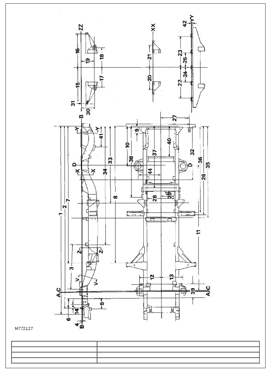
No./Letter
Dimension
A
Front datum
B
Chassis Datum
C
Front axle centre line
|
|
|
Chassis alignment dimensions No./Letter Dimension A Front datum B Chassis Datum C Front axle centre line |