Defender. Manual - part 282


  Index      Land Rover     Land Rover Defender - service manual 2007 year


Search            


Content   ..  280  281  282  283   ..


Defender. Manual - part 282


Safety Belt System - Third Row Safety Belt Buckle

Removal and Installation

Removal

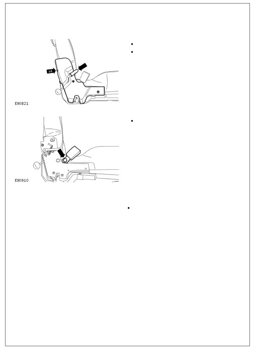
1. Remove the third row seat inner hinge trim panel.

Remove the third row seat recliner handle.

Remove the 4 screws.

2. Remove the third row safety belt buckle.

Remove the bolt.

Installation

1. To install, reverse the removal procedure.

Tighten the bolt to 31 Nm (23 lb.ft).

Safety Belt System - Third Row Safety Belt Retractor

Removal and Installation

Removal

1. Remove the grab handle.

Remove the 2 grab handle screw covers.

Remove the 2 screws.

2. Release the third row safety belt lower anchor.

Remove the bolt.

3. Remove the rear quarter trim panel.

Release the 2 clips.

4. Reposition the C-pillar trim panel.

4. Reposition the C-pillar trim panel.

Remove the 2 lower clips.

Move the C-pillar trim panel upwards to release the 2

upper clips.

5. Remove the third row safety belt retractor.

Remove the 2 bolts.

Installation

1. Install the third row safety belt retractor.

Tighten the bolts to 31 Nm (23 lb.ft).

2. Secure the C-pillar trim panel.

Install the clips.

3. Install the rear quarter trim panel.

Secure with the 2 clips.

4. Secure the third row safety belt lower anchor.

Tighten the bolt to 31 Nm (23 lb.ft).

5. Install the grab handle.

Tighten the screws.

Install the grab handle screw covers.

Body Repairs - General Information - Body Repairs

Description and Operation

General Information

Body shells are of rivetted, bolted and welded construction and are bolted to the chassis frame.

It is essential that design dimensions and strength are restored in accident rectification. It is important that neither

structural weakness nor excessive local stiffness are introduced into the vehicle during body or chassis repair.

Repairs usually involve a combination of operations ranging from straightening procedures to renewal of either individual

panels or panel assemblies. The repairer will determine the repair method and this decision will take into account a

balance of economics between labour and material costs and the availability of repair facilities in both equipment and

skills. It may also involve considerations of vehicles down-time, replacement vehicle availability and repair turn-around

time.

It is expected that a repairer will select the best and most economic repair method possible, making use of the facilities

available. The instructions given are intended to assist a skilled body repairer by expanding approved procedures for

panel replacement with the objective of restoring the vehicle to a safe running condition and effecting a repair which is

visually acceptable and which, even to the experienced eye, does not advertise the fact that it has been damaged.

This does not necessarily mean that the repaired vehicle will be identical in all respects with original factory build. Repair

facilities cannot always duplicate methods of construction used during production.

The panel repairs shown in this section are all based on a 110 Station Wagon. Therefore all illustrations and text relate

only to this model. Although certain areas of the vehicle, such as the front end, are relevant to all models.

Operations covered in this Manual do not include reference to testing the vehicle after repair. It is essential that work is

inspected and suspension geometry checked after completion and if necessary a road test of the vehicle is carried out,

particularly where safety related items are concerned.

Where major units have been disconnected or removed, it is necessary to ensure that fluid levels are checked and

topped up when necessary. It is also necessary to ensure that the repaired vehicle is in a roadworthy condition in

respect of tyre pressures, lights, washer fluid etc.

Body repairs often involve the removal of mechanical and electrical units as well as associated wiring. Where this is

necessary use the relevant section in this manual.

Taking into consideration the differences in body styles, steering and suspension systems as well as engine and

suspension layouts, the location of the following components as applicable to a particular vehicle is critical:

Front suspension upper damper mountings

Front suspension or sub frame mountings

Engine mountings on RH and LH chassis longitudinals

Rear suspension upper damper mountings

Rear suspension mountings or lower pivots

Steering rack mountings

Additional points which can be used to check alignment and assembly are:

Inner holes in cross member - side - main floor

Holes in valance front assembly

Body to chassis mounting holes

Holes in rear floor

Holes in rear lower panels or extension rear floor

Fuel tank mountings

Apertures for windscreen, backlight, bonnet and doors can be checked by offering up an undamaged component as a

gauge and also by measuring known dimensions. 

For additional information, refer to: 

Body and Frame

 (501-26 Body Repairs - Vehicle Specific Information and Tolerance

Checks, Description and Operation).

Straightening

Whenever possible, chassis structural members should be cold straightened under tension. Do not attempt to straighten

with a single pull, but rework the damaged area using a series of pulls, releasing tension between each stage and using

the opportunity to check alignment.

Body jig

Unless damage is limited to cosmetic panels, all repair work to body members must be carried out on a body jig, to

ensure that impact damage has not spread into more remote parts of the body structure. Mounting on a jig will also

ensure that the straightening and panel replacement procedures do not cause further distortion. If original dimensions

cannot be satisfactorily restored by these methods, damaged structural members should be replaced. Damaged areas

should be cut away using a high speed saw, NOT an oxy-acetylene torch.

As a rule, body dimensions are symmetrical about the centre line. A good initial check for distortion is therefore to

measure diagonally and to investigate apparent differences in dimensions.

Inspection

Every accident produces individual differences in damage. Each repair is influenced by the extent of the damage and by

the facilities and equipment available for its rectification.

Most accident damage can be visually inspected and the approximate extent of the damage assessed. Sometimes


Content   ..  280  281  282  283   ..