Defender. Manual - part 208


  Index      Land Rover     Land Rover Defender - service manual 2007 year


Search            


Content   ..  206  207  208  209   ..


Defender. Manual - part 208


Heating and Ventilation - Heater Core

Removal and Installation

Removal

1. Disconnect the battery ground cable. 

For additional information, refer to: 

Battery Disconnect and

Connect

 (414-01 Battery, Mounting and Cables, General

Procedures).

2. Remove the heater core housing. 

For additional information, refer to: 

Heater Core Housing

(412-02 Heating and Ventilation, Removal and Installation).
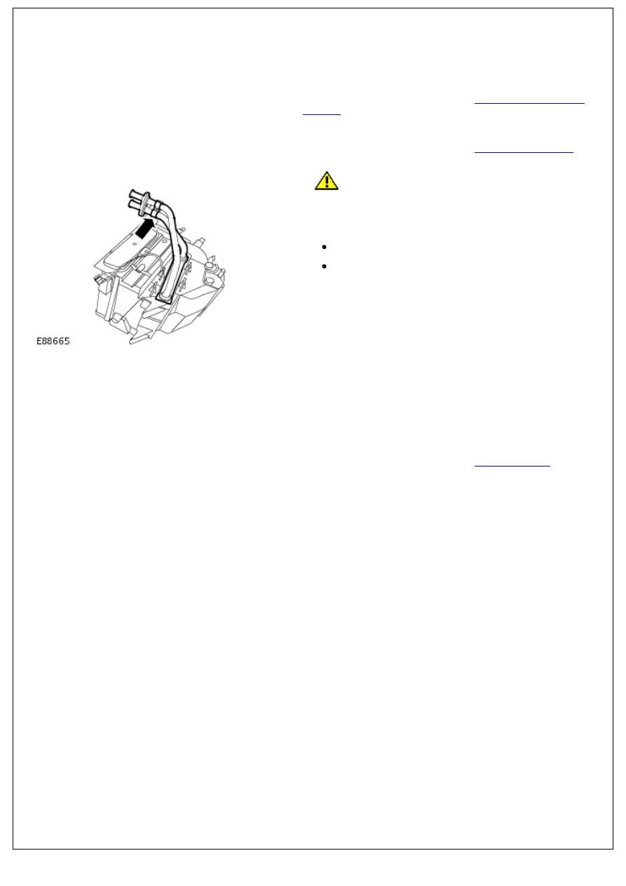
3. 

CAUTION: Make sure no damage occurs to the foam

seal on the heater core. Failure to follow this caution may

result in damage to the component.

Remove the heater core.

Remove the screw.

Remove the pipe clamp.

4. NOTE: Do not disassemble further if the component is

removed for access only.

Remove the grommet from the heater core pipes.

Installation

1. To install, reverse the removal procedure.
2. Connect the battery ground cable. 

For additional information, refer to: 

Battery Connect

 (414-01

Battery, Mounting and Cables, General Procedures).

Heating and Ventilation - Heater Core and Evaporator Core Housing

Removal and Installation

Removal

1. Disconnect the battery ground cable. 

For additional information, refer to: 

Battery Disconnect and

Connect

 (414-01 Battery, Mounting and Cables, General

Procedures).

2. Recover the air conditioning (A/C) refrigerant. 

For additional information, refer to: 

Air Conditioning (A/C)

System Recovery, Evacuation and Charging

 (412-00 Climate

Control System - General Information, General Procedures).

3. Remove the engine control module (ECM). 

For additional information, refer to: 

Engine Control Module

(ECM)

 (303-14 Electronic Engine Controls - 2.4L Duratorq-

TDCi HPCR (103kW/140PS) - Puma, Removal and

Installation).

4. 

CAUTION: Make sure that all openings are sealed. Use

new blanking caps.

Release the thermostatic expansion valve manifold and tube

assembly.

Remove the bolt.

Remove and discard the O-ring seals.

5. Disconnect the heater core hoses.

Using a suitable pipe clamp, clamp the heater hoses.

Release the 2 clips.

6. Remove the instrument panel. 

For additional information, refer to: 

Instrument Panel

 (501-12

Instrument Panel and Console, Removal and Installation).

7. NOTE: Make sure the clips are discarded.

Remove the audio unit support bracket.

Remove and discard the 5 clips.

8. Remove the LH demister duct.

Remove the clip.

9. Release the LH defrost vent duct.

Remove the screw.

10. Remove the LH defrost vent duct.

Remove the clip.

11. Remove the RH demister duct.

Remove the clip.

12. Release the RH defrost vent duct.

12. Release the RH defrost vent duct.

Remove the screw.

13. Remove the RH vent duct.

Remove the clip.

14. Remove the center register duct.

15. Remove the air inlet duct.

Remove the nut.

16. Disconnect the defrost duct blend door control cable.


Content   ..  206  207  208  209   ..