Defender. Manual - part 180


  Index      Land Rover     Land Rover Defender - service manual 2007 year


Search            


Content   ..  178  179  180  181   ..


Defender. Manual - part 180


the intermediate gears

the centre differential assembly

The front and rear output housings are bolted to either side of the main casing.

Mainshaft Input Gear

The transmission output shaft is splined into the mainshaft input gear, which is supported by taper roller bearings.

Input gear bearing pre-load is achieved by the use of a selective shim located in the bearing housing.

Intermediate Gears

The intermediate gear cluster is supported by the taper roller bearings located at each end of the cluster and runs on

the intermediate shaft, which in turn, is supported at the front and rear by the main casing.

Intermediate gear bearing pre-load is achieved by means of a collapsible spacer positioned between the bearings, the

amount of compression applied to the spacer is by means of a nut on the end of the intermediate shaft.

The bore of the intermediate gear is machined with a shoulder at each end to locate the bearings.

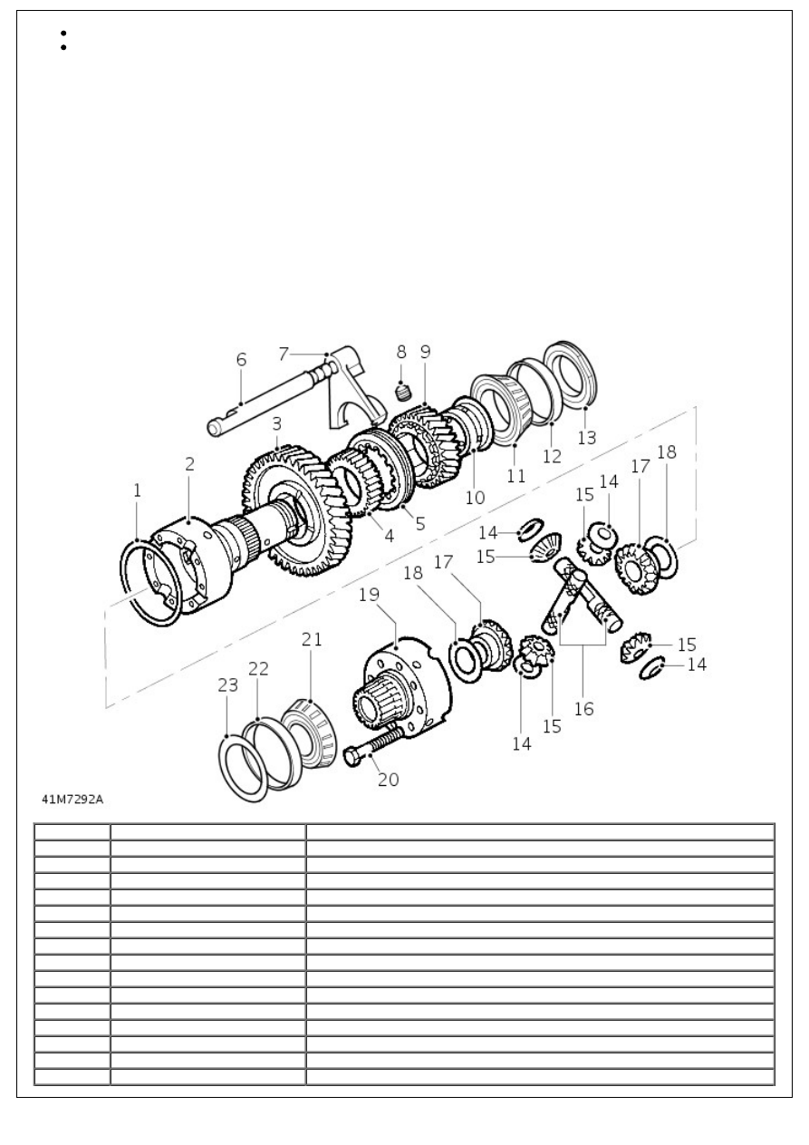
Centre Differential Assembly

Item

Part Number

Description

1

-

Retaining ring

2

-

Differential carrier - rear half

3

-

Low range gear

4

-

High/low hub

5

-

High/low selector sleeve

6

-

High/low selector shaft

7

-

High/low selector fork

8

-

Setscrew - high/low selector fork

9

-

High range gear

10

-

High range gear bush

11

-

Differential rear bearing

12

-

Bearing outer track

13

-

Bearing retaining nut

14

-

Dished thrust washers

15

-

Differential planet gears

16

-

Cross shafts

17

-

Differential side gears

18

-

Selective thrust washers

19

-

Differential carrier - front half

20

-

Bolt - differential carriers

21

-

Differential front bearing

22

-

Bearing outer track

23

-

Selective shim

The centre differential assembly is supported at the front and rear by taper roller bearings, the front bearing outer track

is located in the front output housing and the rear bearing outer track is located in the main casing by the rear output

housing. Bearing pre-load is achieved by means of a selective shim located in the front output housing.

The centre differential rear shaft carries the low range gear, high/low selector sleeve and hub, high range gear and bush

and the differential rear bearing; these components being secured to the shaft by a special staked nut.

The assembly comprises front and rear half carriers with integral shafts connected to differential side gears and planet

gears mounted on cross shafts within the half carriers. Dished, non-selective thrust washers control the engagement of

the planet gears with the differential side gears, whilst selective thrust washers are used to control engagement of the

differential side gears and 'torque to turn' of the differential. The differential carrier halves are bolted together, a

retaining ring providing positive location of the cross shafts.

The high/low selector shaft and fork are located at the side of the differential, movement of the shaft, fork and selector

sleeve being controlled by the high/low selector finger. A spring loaded detent ball fitted in the main casing, locates in

grooves in the shaft.

The selector fork is fitted with a spring assister and clips to reduce the effort required to move the selector lever.

FRONT OUTPUT HOUSING

Item

Part Number

Description

1

-

Hollow plug

2

-

High/low cross shaft housing

3

-

Bolt - high/low cross shaft housing

4

-

O-ring

5

-

High/low cross shaft and lever with cable ball end

6

-

Dog clutch

7

-

Front output shaft

8

-

Differential lock selector shaft

9

-

Front output housing

10

-

Spring and clips - differential lock

11

-

Bolt - Cover plate

12

-

Cover plate

13

-

Differential lock selector fork

14

-

Detent plug and spring - differential lock

15

-

Detent ball - differential lock

16

-

Bolt - front output housing

17

-

Plug

18

-

Circlip

19

-

Output shaft flange and mud shield

20

-

Steel washer

21

-

Self-locking nut

22

-

Felt washer

23

-

Oil seal

24

-

Output shaft bearing

25

-

Bearing spacer

26

-

High/low selector finger

27

-

Differential lock warning indicator switch

28

-

Differential lock selector finger and shaft

29

-

O-rings

30

-

Differential lock selector housing

31

-

Selector lever

32

-

Bolt - housing

33

-

Washer

34

-

Self-locking nut

The front output housing carries:

the front output shaft and flange

the housing and selector

the differential lock selector shaft and fork

Front Output Shaft and Flange

The front output shaft is supported in the housing by a single bearing and is splined into the differential front sun gear.

Housing and Selector Assembly

A high/low cross shaft is located in a housing bolted to the top of the output housing and is connected to the high/low

selector finger, which locates in a slot in the selector shaft.

Differential Lock Selector Shaft and Fork

The differential lock selector housing is bolted to the top of the front output housing, the selector finger passes through

the housing, locating in a slot in the differential lock selector shaft. The differential lock selector shaft passes through

the selector fork, which is located beneath a plate bolted to the side of the output housing. The selector fork engages

the dog clutch sleeve with the differential rear shaft when the splines of the sleeve and differential rear shaft are

aligned. A spring loaded detent ball fitted in the output housing locates in grooves in the shaft.

REAR OUTPUT HOUSING

Item

Part Number

Description

1

-

Rear output shaft

2

-

Rear output housing

3

-

Bolt - rear output housing

4

-

Speedometer drive gear

5

-

Spacer

6

-

Output shaft bearing

7

-

Circlip

8

-

Oil seal

9

-

Mud shield

10

-

Output shaft flange

11

-

Felt washer

12

-

Steel washer

13

-

Self-locking nut

14

-

Transmission brake backplate

15

-

Bolt - transmission brake backplate

16

-

Transmission brake drum

17

-

Countersunk screw

18

-

Speedometer driven gear

19

-

O-ring

20

-

Speedometer driven gear housing

21

-

Seal

22

-

O-ring

23

-

Vehicle speed sensor (if fitted)

24

-

Allen screw (if fitted)

The rear output housing carries the output shaft and flange and the speedometer drive and driven gears. A

mechanically operated transmission brake is attached to the housing, the brake drum being attached to the output

flange.

The rear output shaft is supported in the rear output housing by a single bearing and is splined into the differential rear

shaft. The output shaft also carries the speedometer drive gear, which meshes with the speedometer driven gear

located in the rear output housing.

A differential lock warning lamp switch operated by movement of the selector fork and shaft is screwed into the top of

the output housing.


Content   ..  178  179  180  181   ..