Defender. Manual - part 104


  Index      Land Rover     Land Rover Defender - service manual 2007 year


Search            


Content   ..  102  103  104  105   ..


Defender. Manual - part 104


66. Install the injectors.

Install new sealing washers.

67. CAUTIONS:

 The injector clamp bolts must only be used two times.

 Tighten the bolts in the stages shown.

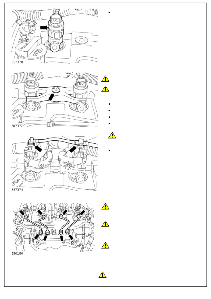
Secure the injectors.

Install the injector clamps.

Stage 1: Tighten the bolts to 6 Nm (4 lb.ft).

Stage 2: 180 degrees.

Install the injector clamp covers.

68. 

CAUTION: Remove and discard the blanking caps.

Connect the injector spill rail.

Install the clips.

69. CAUTIONS:

 Maintain pressure on the high-pressure fuel supply line

to keep the olives in contact with the fuel injectors and the

fuel rail cones while installing unions.

 Do not allow the unions to hit the olive ends of the

high-pressure fuel supply line as this may damage the ends of

the high-pressure fuel supply line and allow foreign matter to

enter the fuel injection system.

 Only tighten the unions finger-tight at this stage.

• NOTE: Remove and discard the blanking caps.

Install the new high-pressure fuel supply lines.

70. CAUTIONS:

 Tighten the high-pressure fuel supply lines in the stages

shown.

 Remove and discard the blanking caps.

Secure the high-pressure fuel supply lines.

Stage 1: Tighten the high-pressure fuel supply line

unions at the fuel injectors and the fuel injection pump

to 35 Nm (26 lb.ft).

Stage 2: Tighten the high-pressure fuel supply line clips

to 10 Nm (7 lb.ft).

Stage 3: Tighten the fuel rail bolts to 23 Nm (17 lb.ft).

Stage 4: Tighten the high-pressure fuel supply line

unions at the fuel rail to 35 Nm (26 lb.ft).

71. Install the engine wiring harness.
72. Connect the glow plug wiring harness.

Tighten the nuts to 2 Nm (1 lb.ft).

73. Secure the engine wiring harness support bracket.

Tighten nut to 10 Nm (7 lb.ft).

Tighten bolt to 10 Nm (7 lb.ft).

74. Connect the injector electrical connectors.

Secure the injector wiring harness.

Secure the clips.

75. Connect the fuel rail pressure sensor (FRP) electrical

75. Connect the fuel rail pressure sensor (FRP) electrical

connector.

76. NOTE: Make sure the engine wiring harness is routed

correctly.

Install the engine cover.

Tighten the bolts to 10 Nm (7 lb.ft).

77. 

CAUTION: Remove and discard the blanking caps.

Install the turbocharger oil return tube.

Install a new O-ring seal.

Install the clamp.

Tighten the bolt to 22 Nm (16 lb.ft).

78. Install the RH engine mount bracket.

Tighten the bolts to 63 Nm (46lb.ft).

CAUTION: New nuts must be installed.

79. 

CAUTION: New nuts must be installed.

• NOTE: Clean the component mating faces.

Install the exhaust manifold and turbocharger assembly.

Install a new gasket.

Tighten the nuts to 40 Nm (30 lb.ft).

Tighten the bolts to 40 Nm (30 lb.ft).

80. Secure the turbocharger oil return pipe.

Install a new gasket.

Tighten the bolts to 10 Nm (7 lb.ft).

81. 

CAUTION: Remove and discard the blanking caps.

Install the oil level indicator and the oil level indicator tube.

Install a new O-ring seal.

Tighten the bolt to 10 Nm (7 lb.ft).

Secure the wiring harness.

82. 

CAUTION: Remove and discard the blanking caps.

• NOTE: Clean the component mating faces.

Connect the turbocharger oil feed pipe.

Install new sealing washers.

Tighten the banjo bolt to 35 Nm (26 lb.ft).

83. Connect the breather pipe.


Content   ..  102  103  104  105   ..