Defender. Manual - part 101


  Index      Land Rover     Land Rover Defender - service manual 2007 year


Search            


Content   ..  99  100  101  102   ..


Defender. Manual - part 101


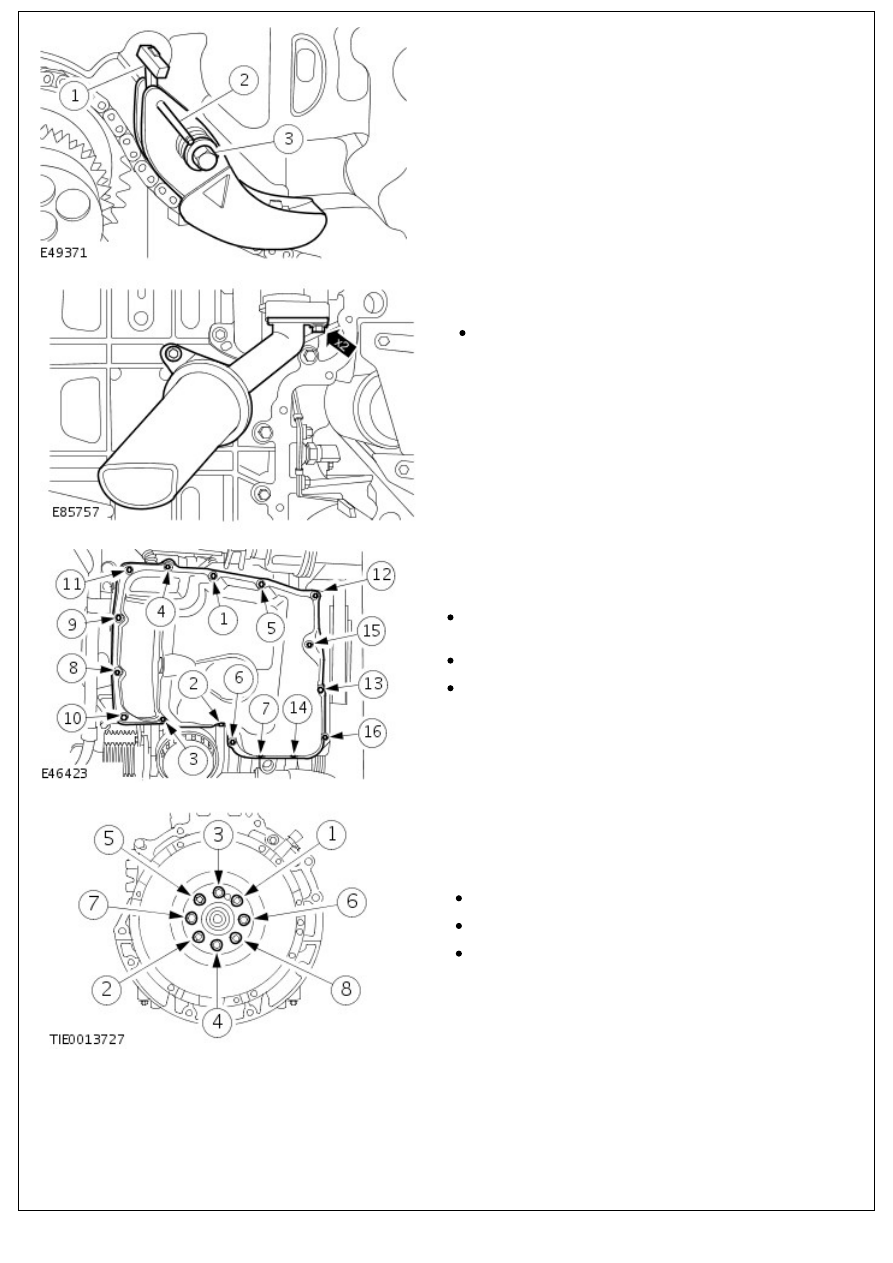
17. Install the oil pump chain tensioner.

1. Install the spring to the stud.

2. Unlock the tensioner by removing the pin.

3. Tighten the bolt 22 Nm (16 lb.ft).

18. NOTE: Install a new O-ring seal.

Install the oil pump pickup tube.

Tighten the bolts to 10 Nm (7 lb.ft).

19. NOTE: Tighten the bolts in the sequence shown in two

stages.

Install the new oil pan.

Apply a 3 mm bead of the specified sealant to the oil

pan.

Stage 1: Tighten bolts 1 through 16 to 7 Nm.

Stage 2: Tighten bolts 1 through 16 to 14 Nm.

20. NOTE: Install new flywheel bolts.

• NOTE: Tighten the bolts in the sequence shown in three

stages.

Install the flywheel.

Stage 1: 25 Nm (18 lb.ft).

Stage 2: 40 Nm (30 lb.ft).

Stage 3: 48 degrees.

21. NOTE: Tighten the bolts in the sequence shown.

21. NOTE: Tighten the bolts in the sequence shown.

Using the special tool, install the clutch disc and pressure

plate.

Tighten the bolts to 29 Nm (21 lb.ft).

22. NOTE: Do not fully tighten the crankshaft position sensor

bracket bolts at this stage.

Install the crankshaft position (CKP) sensor bracket.

23. NOTE: After installation do not move the special tool.

Install the special tool.

24. Rotate the crankshaft until piston number one is

approximately 10 mm before top dead center (BTDC).

25. Position a dial gauge on the cylinder block.

Position the dial indicator gauge plunger on to piston

number 1.

Zero the dial indicator gauge.

26. Mark the position on the flywheel.

27. NOTE: Rotate the flywheel counterclockwise.

Rotate the crankshaft until the piston number one achieves

zero on the dial indicator gauge.

Mark the position on the flywheel.

28. Repeat the previous steps to make sure that the marking is

correct.

29. NOTE: The middle of the markings is top dead center

(TDC).

Measure the distance between the two marks.

30. Divide the amount by two and mark the TDC position on

the flywheel primary mass.

31. Measure the circumference of the flywheel.

32. NOTE: Mark the calculated amount on the flywheel by

measuring from TDC counterclockwise.

Multiply the circumference by 0.1388.

1. First mark.

2. Second mark.

3. Determined TDC.

4. Determined 50 degrees BTDC.

33. NOTE: Rotate the crankshaft in the normal direction of

rotation to the mark of the calculated 50 degrees BTDC.

Install the special tool.

34. Secure the crankshaft position (CKP) sensor bracket.

34. Secure the crankshaft position (CKP) sensor bracket.

Tighten the bolts to 23 Nm (17 lb.ft).

35. NOTE: Clean the component mating face.

• NOTE: Measure the piston protrusion of each cylinder at TDC.

• NOTE: The largest measurement determines the choice of the

cylinder head gasket.

Measure the distance between the piston crown and the

cylinder block at the points indicated.

Using the specification table determine the correct

cylinder head gasket. 

For additional information, refer to: 

Specifications

 (303-

01 Engine - 2.4L Duratorq-TDCi HPCR (103kW/140PS) -

Puma, Specifications).

36. 

CAUTION: The thickness of the new cylinder head

gasket depends on the piston protrusion (hole/tooth marked).

Install a new cylinder head gasket.

CAUTION: Install new cylinder head bolts.


Content   ..  99  100  101  102   ..