Jeep Grand Cherokee L (2024 year). Manual in english - page 9
 

  Index      Manuals     Jeep Grand Cherokee L (2024 year). Manual in english


Search            copyright infringement  


Content      ..     7      8      9     


Jeep Grand Cherokee L (2024 year). Manual in english - page 9


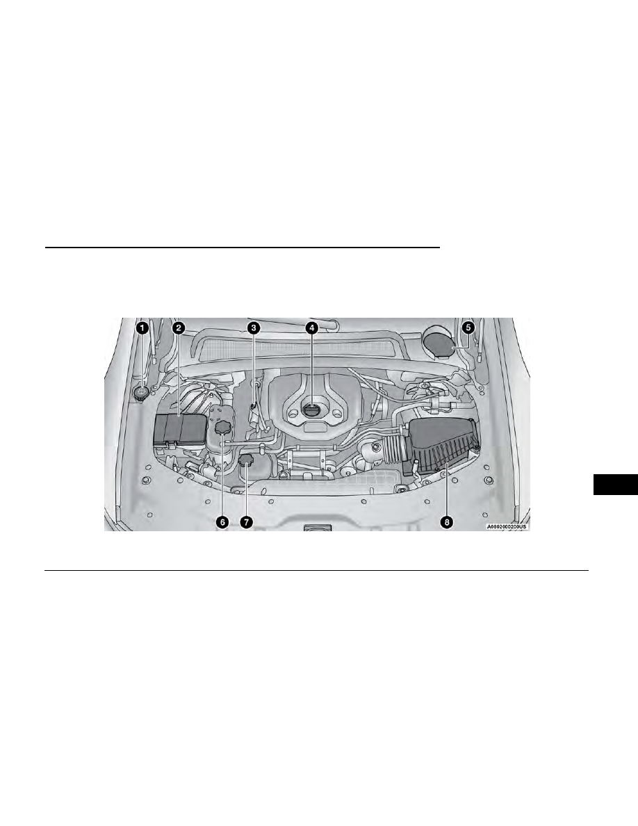
ENGINE COMPARTMENT

2.0L ENGINE

1 — Washer Fluid Reservoir Cap

5 — Brake Fluid Reservoir Access

2 — Power Distribution Center (Fuses)

6 — Engine Coolant Pressure Cap

3 — Engine Oil Dipstick

7 — Intercooler Coolant Reservoir Cap

4 — Engine Oil Fill

8 — Engine Air Cleaner, Filter

SERVICING AND MAINTENANCE

273

8

3.6L ENGINE

1 — Washer Fluid Reservoir Cap

5 — Engine Oil Fill

2 — Power Distribution Center (Fuses)

6 — Brake Fluid Reservoir Access

3 — Engine Coolant Pressure Cap

7 — Engine Air Cleaner, Filter

4 — Engine Oil Dipstick

274

SERVICING AND MAINTENANCE

5.7L ENGINE

1 — Washer Fluid Reservoir Cap

5 — Brake Fluid Reservoir Access

2 — Power Distribution Center (Fuses)

6 — Engine Oil Dipstick

3 — Engine Coolant Pressure Cap

7 — Engine Air Cleaner, Filter

4 — Engine Oil Fill

SERVICING AND MAINTENANCE

275

8

CHECKING OIL LEVEL

To ensure proper engine lubrication, the engine oil must
be maintained at the correct level. Check the oil level at
regular intervals, such as every fuel stop. The best time
to check the engine oil level is about five minutes after
a fully warmed up engine is shut off.

Checking the oil while the vehicle is on level ground will
improve the accuracy of the oil level readings.

There are four possible dipstick types:

Crosshatched zone.

Crosshatched zone marked SAFE.

Crosshatched zone marked with MIN at the low end
of the range and MAX at the high end of the range.

Crosshatched zone marked with dimples at the MIN
and the MAX ends of the range.

NOTE:

Always maintain the oil level within the crosshatch
markings on the dipstick.

Adding 1 qt (1.0 L) of oil when the reading is at the low
end of the dipstick range will raise the oil level to the
high end of the range marking.

NOTE:

Always maintain the oil level within the crosshatch
markings on the dipstick.

NOTE:

Use care when filling under hood fluids such as engine
oil, washer fluid, antifreeze, etc., to minimize spillage
onto the top of the engine. Any excess fluid that is
spilled onto the top of the engine should be removed
using compressed air or an absorbent cloth.

ADDING WASHER FLUID

The instrument cluster display will indicate when the
washer fluid level is low. When the sensor detects a low
fluid level, the Low Washer Fluid Warning Light will illu-
minate and the “Washer Fluid Low” message will
display.

The fluid reservoir for the windshield washers and the
rear window washer is shared. The fluid reservoir is
located in the engine compartment, be sure to check
the fluid level at regular intervals. Fill the reservoir with
windshield washer solvent only (not radiator antifreeze).
When refilling the washer fluid reservoir, take some
washer fluid and apply it to a cloth or towel and wipe
clean the wiper blades, this will help blade perfor-
mance. To prevent freeze-up of your windshield washer
system in cold weather, select a solution or mixture that
meets or exceeds the temperature range of your cli-
mate. This rating information can be found on most
washer fluid containers.

NOTE:

Use care when filling under hood fluids such as engine
oil, washer fluid, antifreeze, etc., to minimize spillage
onto the top of the engine. Any excess fluid that is
spilled onto the top of the engine should be removed
using compressed air or an absorbent cloth.

WARNING!

Commercially available windshield washer solvents
are flammable. They could ignite and burn you. Care
must be exercised when filling or working around the
washer solution.

CAUTION!

Do not travel with the windshield washer fluid reser-
voir empty: the windshield washers are essential for
improving visibility.

MAINTENANCE-FREE BATTERY

Your vehicle is equipped with a maintenance-free bat-
tery. Water will never have to be added, and periodic
maintenance is not required.

WARNING!

Battery fluid is a corrosive acid solution and can
burn or even blind you. Do not allow battery fluid to
contact your eyes, skin, or clothing. Do not lean
over a battery when attaching clamps. If acid
splashes in eyes or on skin, flush the area immedi-
ately with large amounts of water. Refer to Jump
Starting Procedure

page 264.

Battery gas is flammable and explosive. Keep
flame or sparks away from the battery. Do not use
a booster battery or any other booster source with
an output greater than 12 Volts. Do not allow cable
clamps to touch each other.

Battery posts, terminals, and related accessories
contain lead and lead compounds. Wash hands
after handling.

276

SERVICING AND MAINTENANCE

CAUTION!

It is essential when replacing the cables on the
battery that the positive cable is attached to the
positive post and the negative cable is attached to
the negative post. Battery posts are marked posi-
tive (+) and negative (-) and are identified on the
battery case. Cable clamps should be tight on the
terminal posts and free of corrosion.

If a “fast charger” is used while the battery is in
the vehicle, disconnect both vehicle battery cables
before connecting the charger to the battery. Do
not use a “fast charger” to provide starting voltage.

PRESSURE WASHING

Cleaning the engine compartment with a high pressure
washer is not recommended.

CAUTION!

Precautions have been taken to safeguard all parts
and connections however, the pressures generated
by these machines is such that complete protection
against water ingress cannot be guaranteed.

VEHICLE MAINTENANCE

An authorized dealer has the qualified service person-
nel, special tools, and equipment to perform all service
operations in an expert manner. Service Manuals are
available which include detailed service information for
your vehicle. Refer to these Service Manuals before
attempting any procedure yourself.

NOTE:

Intentional tampering with emissions control systems
may void your warranty and could result in civil penal-
ties being assessed against you.

WARNING!

You can be badly injured working on or around a
motor vehicle. Only do service work for which you
have the knowledge and the proper equipment. If you
have any doubt about your ability to perform a service
job, take your vehicle to a competent mechanic.

ENGINE OIL

Engine Oil Selection

Use only the manufacturer's recommended fluid

page 324.

NOTE:

Hemi engines at times can tick right after startup and
then quiet down after approximately 30 seconds. This is
normal and will not harm the engine. This characteristic
can be caused by short drive cycles. For example, if the
vehicle is started then shut off after driving a short dis-
tance. Upon restarting, you may experience a ticking
sound. Other causes could be if the vehicle is unused
for an extended period of time, incorrect oil, extended
oil changes or extended idling. If the engine continues
to tick or if the Malfunction Indicator Light (MIL) comes
on, see the nearest authorized dealer.

American Petroleum Institute (API)

Approved Engine Oil

These symbols mean that the oil has been certified by
the API. The manufacturer only recommends API trade-
mark oils.

The API Starburst trademark certifies
0W-20, 0W-30 and 5W-30 engine oils.

The API Donut trademark certifies
0W-40 and 5W-40 engine oil.

CAUTION!

Do not use chemical flushes in your engine oil as the
chemicals can damage your engine. Such damage is
not covered by the New Vehicle Limited Warranty.

Synthetic Engine Oils

Your engine was designed for synthetic engine oils, only
use synthetic API approved engine oils.

Synthetic engine oils which do not have both the correct
API trademark and the correct SAE viscosity grade num-
bers should not be used.

Materials Added To Engine Oil

The manufacturer strongly recommends against the
addition of any additives (other than leak detection
dyes) to the engine oil. Engine oil is an engineered prod-
uct and its performance may be impaired by supple-
mental additives.

SERVICING AND MAINTENANCE

277

8

Disposing Of Used Engine Oil And Oil

Filters

Care should be taken in disposing of used engine oil
and oil filters from your vehicle. Used oil and oil filters,
indiscriminately discarded, can present a problem to
the environment. Contact an authorized dealer, service
station or governmental agency for advice on how and
where used oil and oil filters can be safely discarded in
your area.

ENGINE OIL FILTER

The engine oil filter should be replaced with a new filter
at every engine oil change.

Engine Oil Filter Selection

A full-flow type disposable oil filter should be used for
replacement. The quality of replacement filters varies
considerably. Only high quality Mopar® filters should be
used. If Mopar® Engine Oil Filters are unavailable, only
use filters that meet or exceed SAE/USCAR-36 Filter
Performance Requirements.

ENGINE AIR CLEANER FILTER

For the proper maintenance intervals

page 270.

WARNING!

The air induction system (air cleaner, hoses, etc.) can
provide a measure of protection in the case of engine
backfire. Do not remove the air induction system (air
cleaner, hoses, etc.) unless such removal is neces-
sary for repair or maintenance. Make sure that no
one is near the engine compartment before starting
the vehicle with the air induction system (air cleaner,
hoses, etc.) removed. Failure to do so can result in
serious personal injury.

Engine Air Cleaner Filter Selection

The quality of replacement engine air cleaner filters
varies considerably. Only high quality Mopar® filters
should be used.

Engine Air Cleaner Filter Inspection and

Replacement

Engine Air Cleaner Filter Removal

1. With a suitable tool, fully loosen fasteners on the

engine air cleaner filter cover.

2. Lift the engine air cleaner filter cover and rotate

hinge to access the air cleaner filter.

3. Remove the engine air cleaner filter from the hous-

ing assembly.

Engine Air Cleaner Filter Installation

NOTE:

Inspect and clean the housing assembly if significant
dirt or debris is present before replacing the engine air
cleaner filter.

1. Install the engine air cleaner filter into the housing

assembly with the engine air cleaner filter inspec-
tion surface facing downward.

2. Install the engine air cleaner filter cover onto the

housing assembly locating tabs.

3. Tighten the fasteners on the engine air cleaner filter

assembly.

CAUTION!

Do not overtighten the engine air cleaner filter cover
lid screws or damage may result.

AIR CONDITIONER MAINTENANCE

For best possible performance, your air conditioner
should be checked and serviced by an authorized
dealer at the start of each warm season. This service
should include cleaning of the condenser fins and a
performance test. Drive belt tension should also be
checked at this time.

Engine Air Cleaner Filter Cover

1 — Engine Air Cleaner Filter Cover
2 — Fasteners

278

SERVICING AND MAINTENANCE

WARNING!

Use only refrigerants and compressor lubricants
approved by the manufacturer for your air condi-
tioning system. Some unapproved refrigerants are
flammable and can explode, injuring you. Other
unapproved refrigerants or lubricants can cause
the system to fail, requiring costly repairs. Refer to
Warranty Information Book, for further warranty
information.

The air conditioning system contains refrigerant
under high pressure. To avoid risk of personal
injury or damage to the system, adding refrigerant
or any repair requiring lines to be disconnected
should be done by an experienced technician.

CAUTION!

Do not use chemical flushes in your air conditioning
system as the chemicals can damage your air condi-
tioning components. Such damage is not covered by
the New Vehicle Limited Warranty.

Refrigerant Recovery And Recycling —

R–1234yf

R–1234yf Air Conditioning Refrigerant is a Hydrofluo-
roolefin (HFO) that is endorsed by the Environmental
Protection Agency and is an ozone-friendly substance
with a low global-warming potential. The manufacturer
recommends that air conditioning service be performed
by an authorized dealer using recovery and recycling
equipment.

NOTE:

Use only manufacturer approved A/C system PAG com-
pressor oil, and refrigerants.

Cabin Air Filter Replacement

For the proper maintenance intervals

page 270.

WARNING!

Do not remove the cabin air filter while the vehicle is
running, or while the ignition is in the ON/RUN mode.
With the cabin air filter removed and the blower operat-
ing, the blower can contact hands and may propel dirt
and debris into your eyes, resulting in personal injury.

The cabin air filter is located in the fresh air inlet behind
the glove compartment. Perform the following proce-
dure to replace the filter:

1. Open the glove compartment and remove all contents.
2. There is a glove compartment travel stop on the

right side of the glove compartment door. Partially
close the glove compartment door and pull the
travel stop toward you to release the glove compart-
ment travel stop.

3. With the glove compartment door loose, remove the

glove compartment tension tether and tether clip by
sliding the clip toward the face of the glove compart-
ment door and lifting the clip out of glove compart-
ment door.

4. Lower the glove compartment door to the floor.

5. Squeeze the retaining tabs together that secures

the cabin air filter cover to the HVAC housing.
Unhinge the filter cover on the right side to fully
remove the cover.

Glove Compartment

1 — Glove Compartment Travel Stop
2 — Glove Compartment Door

Side Of Glove Compartment

1 — Glove Compartment Tension Tether
2 — Glove Compartment Door

SERVICING AND MAINTENANCE

279

8

6. Remove the cabin air filter by pulling it straight out

of the housing.

7. Install the cabin air filter with the arrow on the filter

pointing toward the floor. When installing the filter
cover, make sure the retaining tabs fully engage into
the HVAC housing.

CAUTION!

The cabin air filter is identified with an arrow to indi-
cate airflow direction through the filter. Failure to
properly install the filter will result in the need to
replace it more often.

8. Lift the glove compartment door up and reattach

the tension tether by inserting the tether clip in the
glove compartment and sliding the clip away from
the face of the glove compartment door.

9. Push the door to the near closed position to reen-

gage the glove compartment travel stops.

NOTE:

Ensure the glove compartment travel stops are fully
engaged.

ACCESSORY DRIVE BELT
INSPECTION

WARNING!

Do not attempt to inspect an accessory drive belt
with vehicle running.

When working near the radiator cooling fan, dis-
connect the fan motor lead. The fan is temperature
controlled and can start at any time regardless of
ignition mode. You could be injured by the moving
fan blades.

You can be badly injured working on or around a
motor vehicle. Only do service work for which you
have the knowledge and the proper equipment. If
you have any doubt about your ability to perform a
service job, take your vehicle to a competent
mechanic.

When inspecting accessory drive belts, small cracks
that run across ribbed surface of belt from rib to rib, are
considered normal. These are not a reason to replace
belt. However, cracks running along a rib (not across)
are not normal. Any belt with cracks running along a rib
must be replaced. Also have the belt replaced if it has
excessive wear, frayed cords or severe glazing.

Conditions that would require replacement:

Rib chunking (one or more ribs has separated from
belt body)

Rib or belt wear

Longitudinal belt cracking (cracks between two ribs)

Belt slips

Groove jumping (belt does not maintain correct posi-
tion on pulley)

Belt broken (identify and correct problem before
new belt is installed)

Noise (objectionable squeal, squeak, or rumble is
heard or felt while drive belt is in operation)

Some conditions can be caused by a faulty component
such as a belt pulley. Belt pulleys should be carefully
inspected for damage and proper alignment.

Belt replacement on some models requires the use of
special tools, we recommend having your vehicle ser-
viced at an authorized dealer.

Cabin Air Filter Cover

1 — Retaining Tabs

Accessory Belt (Serpentine Belt)

280

SERVICING AND MAINTENANCE

BODY LUBRICATION

Locks and all body pivot points, including such items as
seat tracks, door hinge pivot points and rollers, liftgate,
tailgate, decklid, sliding doors and hood hinges, should
be lubricated periodically with a lithium-based grease,
such as Mopar® Spray White Lube to ensure quiet,
easy operation and to protect against rust and wear.
Prior to the application of any lubricant, the parts con-
cerned should be wiped clean to remove dust and grit;
after lubricating excess oil and grease should be
removed. Particular attention should also be given to
hood latching components to ensure proper function.
When performing other underhood services, the hood
latch, release mechanism and safety catch should be
cleaned and lubricated.

The external lock cylinders should be lubricated twice a
year, preferably in the Autumn and Spring. Apply a small
amount of a high quality lubricant, such as Mopar®
Lock Cylinder Lubricant directly into the lock cylinder.

WINDSHIELD WIPER BLADES

Clean the rubber edges of the wiper blades and the
windshield periodically with a sponge or soft cloth and
a mild nonabrasive cleaner. This will remove accumula-
tions of salt or road film.

Operation of the wipers on dry glass for long periods
may cause deterioration of the wiper blades. Always
use washer fluid when using the wipers to remove salt
or dirt from a dry windshield.

Avoid using the wiper blades to remove frost or ice from
the windshield. Keep the blade rubber out of contact
with petroleum products such as engine oil, gasoline,
etc.

NOTE:

Life expectancy of wiper blades varies depending on
geographical area and frequency of use. Poor perfor-
mance of blades may be present with chattering,
marks, water lines or wet spots. If any of these condi-
tions are present, clean the wiper blades or replace as
necessary.

The wiper blades and wiper arms should be inspected
periodically, not just when wiper performance problems
are experienced. This inspection should include the
following points:

Wear or uneven edges

Foreign material

Hardening or cracking

Deformation or fatigue

If a wiper blade or wiper arm is damaged, replace the
affected wiper arm or blade with a new unit. Do not
attempt to repair a wiper arm or blade that is damaged.

Front Wiper Blade Removal/Installation

CAUTION!

Do not allow the wiper arm to spring back against the
glass without the wiper blade in place or the glass
may be damaged.

1. Lift the wiper arm to raise the wiper blade off of the

glass, until the wiper arm is in the full up position.

2. To disengage the wiper blade from the wiper arm,

flip up the release tab on the wiper blade and while
holding the wiper arm with one hand, slide the wiper
blade down towards the base of the wiper arm.

Wiper Blade With Release Tab In Locked Position

1 — Wiper
2 — Release Tab
3 — Wiper Arm

SERVICING AND MAINTENANCE

281

8

3. With the wiper blade disengaged, remove the wiper

blade from the wiper arm by holding the wiper arm
with one hand and separating the wiper blade from
the wiper arm with the other hand (move the wiper
blade toward the right side of the vehicle to sepa-
rate the wiper blade from the wiper arm).

4. Gently lower the wiper arm onto the glass.

Installing The Front Wipers

1. Lift the wiper arm off of the glass, until the wiper

arm is in the full up position.

2. Position the wiper blade near the hook on the tip of

the wiper arm with the wiper release tab open and
the blade side of the wiper facing up and away from
the windshield.

3. Insert the hook on the tip of the arm through the

opening in the wiper blade under the release tab.

4. Slide the wiper blade up into the hook on the wiper

arm and rotate the wiper blade until it is flush
against the wiper arm. Fold down the latch release
tab and snap it into its locked position. Latch
engagement will be accompanied by an audible
click.

5. Gently lower the wiper blade onto the glass.

Rear Wiper Blade Removal/Installation

1. Lift the rear wiper arm fully off the glass.

2. To remove the wiper blade from the wiper arm, grab

the bottom end of the wiper blade nearest to wiper
arm with your left hand. With your right hand, hold
the wiper arm as you pull the wiper blade away from
the wiper arm past its stop (far enough to unsnap
the wiper blade pivot from the receptacle on the end
of the wiper arm).

NOTE:

Resistance will be accompanied by an audible
snap.

The wiper arm does not stay in the service up
position.

Wiper Blade With Release Tab In Unlocked Position

1 — Wiper Blade
2 — Release Tab
3 — Wiper Arm

Wiper Blade Removed From Wiper Arm

1 — Wiper Blade
2 — Release Tab
3 — Wiper Arm

Wiper Blade In Folded Out Position

1 — Wiper Blade
2 — Wiper Arm

282

SERVICING AND MAINTENANCE

3. Still grabbing the bottom end of the wiper blade,

move the wiper blade upward and away from the
wiper arm to disengage.

4. Gently lower the tip of the wiper arm onto the glass.

Installing The Rear Wiper

1. Lift the rear wiper arm fully off the glass.

2. Insert the wiper blade pivot pin into the opening on

the end of the wiper arm. Grab the bottom end of
the wiper arm with one hand, and press the wiper
blade flush with the wiper arm until it snaps into
place.

3. Lower the wiper blade onto the glass.

EXHAUST SYSTEM

The best protection against carbon monoxide entry into
the vehicle body is a properly maintained engine
exhaust system.

If you notice a change in the sound of the exhaust sys-
tem; or if exhaust fumes can be detected inside the
vehicle; or when the underside or rear of the vehicle is
damaged; have an authorized technician inspect the
complete exhaust system and adjacent body areas for
broken, damaged, deteriorated, or mispositioned parts.
Open seams or loose connections could permit exhaust
fumes to seep into the passenger compartment. In
addition, have the exhaust system inspected each time
the vehicle is raised for lubrication or oil changes.
Replace as required.

WARNING!

Exhaust gases can injure or kill. They contain Car-
bon Monoxide (CO), which is colorless and odor-
less. Breathing it can make you unconscious and
can eventually poison you. To avoid breathing CO

page 248.

A hot exhaust system can start a fire if you park
over materials that can burn. Such materials might
be grass or leaves coming into contact with your
exhaust system. Do not park or operate your
vehicle in areas where your exhaust system can
contact anything that can burn.

CAUTION!

The catalytic converter requires the use of
unleaded fuel only. Leaded gasoline will destroy
the effectiveness of the catalyst as an emissions
control device and may seriously reduce engine
performance and cause serious damage to the
engine.

Damage to the catalytic converter can result if your
vehicle is not kept in proper operating condition. In
the event of engine malfunction, particularly involv-
ing engine misfire or other apparent loss of perfor-
mance, have your vehicle serviced promptly. Con-
tinued operation of your vehicle with a severe
malfunction could cause the converter to overheat,
resulting in possible damage to the converter and
vehicle.

Under normal operating conditions, the catalytic con-
verter will not require maintenance. However, it is
important to keep the engine properly tuned to ensure
proper catalyst operation and prevent possible catalyst
damage.

NOTE:

Intentional tampering with emissions control systems
can result in civil penalties being assessed against you.

In unusual situations involving grossly malfunctioning
engine operation, a scorching odor may suggest severe
and abnormal catalyst overheating. If this occurs, stop
the vehicle, turn off the engine and allow it to cool. Ser-
vice, including a tune-up to manufacturer's specifica-
tions, should be obtained immediately.

Wiper Blade Removed From Wiper Arm

1 — Wiper Blade
2 — Wiper Arm

SERVICING AND MAINTENANCE

283

8

To minimize the possibility of catalytic converter
damage:

Do not interrupt the ignition when the transmission
is in gear and the vehicle is in motion.

Do not try to start the vehicle by pushing or towing
the vehicle.

Do not idle the engine with any ignition components
disconnected or removed, such as during diagnostic
testing, or for prolonged periods during very rough
idle or malfunctioning operating conditions.

COOLING SYSTEM

WARNING!

You or others can be badly burned by hot engine
coolant (antifreeze) or steam from your radiator. If
you see or hear steam coming from under the
hood, do not open the hood until the radiator has
had time to cool. Never open a cooling system
pressure cap when the radiator or coolant bottle is
hot.

Keep hands, tools, clothing, and jewelry away from
the radiator cooling fan when the hood is raised.
The fan starts automatically and may start at any
time, whether the engine is running or not.

When working near the radiator cooling fan, dis-
connect the fan motor lead or turn the ignition to
the OFF position. The fan is temperature controlled
and can start at any time the ignition is in the ON
position.

Engine Coolant Checks

Check the engine coolant (antifreeze) protection every
12 months (before the onset of freezing weather, where
applicable). If the engine coolant is dirty, the system
should be drained, flushed, and refilled with fresh
Organic Additive Technology (OAT) coolant (conforming
to MS.90032) by an authorized dealer. Check the front
of the A/C condenser for any accumulation of bugs,
leaves, etc. If dirty, clean by gently spraying water from
a garden hose vertically down the face of the
condenser.

Check the engine cooling system hoses for brittle rub-
ber, cracking, tears, cuts, and tightness of the connec-
tion at the coolant recovery bottle and radiator. Inspect
the entire system for leaks. DO NOT REMOVE THE
COOLANT PRESSURE CAP WHEN THE COOLING SYSTEM
IS HOT.

Cooling System — Drain, Flush And Refill

NOTE:

Some vehicles require special tools to add coolant prop-
erly. Failure to fill these systems properly could lead to
severe internal engine damage. If any coolant is needed
to be added to the system please contact an authorized
dealer.

If the engine coolant (antifreeze) is dirty or contains
visible sediment, have an authorized dealer clean and
flush with Organic Additive Technology (OAT) coolant
(conforming to MS.90032).

For the proper maintenance intervals

page 270.

Selection Of Coolant

Refer to Engine Fluids And Lubricants

page 324.

NOTE:

Mixing of engine coolant (antifreeze) other than
specified Organic Additive Technology (OAT) engine
coolant, may result in engine damage and may
decrease corrosion protection. OAT engine coolant is
different and should not be mixed with Hybrid
Organic Additive Technology (HOAT) engine coolant
or any “globally compatible” coolant. If a non-OAT
engine coolant is introduced into the cooling system
in an emergency, the cooling system will need to be
drained, flushed, and refilled with fresh OAT coolant
(conforming to MS.90032), by an authorized dealer
as soon as possible.

Do not use water alone or alcohol-based engine
coolant products. Do not use additional rust inhibi-
tors or antirust products, as they may not be com-
patible with the radiator engine coolant and may
plug the radiator.

This vehicle has not been designed for use with pro-
pylene glycol-based engine coolant. Use of propyl-
ene glycol-based engine coolant is not
recommended.

Some vehicles require special tools to add coolant
properly. Failure to fill these systems properly could
lead to severe internal engine damage. If any cool-
ant is needed to be added to the system please con-
tact an authorized dealer.

284

SERVICING AND MAINTENANCE

Adding Coolant

Your vehicle has been built with an improved engine
coolant (OAT coolant conforming to MS.90032) that
allows extended maintenance intervals. This engine
coolant (antifreeze) can be used up to 10 years or
150,000 miles (240,000 km) before replacement. To
prevent reducing this extended maintenance period, it
is important to use the same engine coolant (OAT cool-
ant conforming to MS.90032) throughout the life of
your vehicle.

Please review these recommendations for using
Organic Additive Technology (OAT) engine coolant that
meets the requirements of the manufacturer Material
Standard MS.90032. When adding engine coolant:

We recommend using Mopar® Antifreeze/Coolant
10 Year/150,000 Mile (240,000 km) Formula OAT
that meets the requirements of the manufacturer
Material Standard MS.90032.

Mix a minimum solution of 50% OAT engine coolant
that meets the requirements of the manufacturer
Material Standard MS.90032 and distilled water.
Use higher concentrations (not to exceed 70%) if
temperatures below −34°F (−37°C) are anticipated.
Please contact an authorized dealer for assistance.

Use only high purity water such as distilled or deion-
ized water when mixing the water/engine coolant
solution. The use of lower quality water will reduce
the amount of corrosion protection in the engine
cooling system.

NOTE:

It is the owner's responsibility to maintain the proper
level of protection against freezing according to the
temperatures occurring in the area where the
vehicle is operated.

Use care when filling under hood fluids such as
engine oil, washer fluid, antifreeze, etc., to minimize
spillage onto the top of the engine. Any excess fluid
that is spilled onto the top of the engine should be
removed using compressed air or an absorbent cloth.

Some vehicles require special tools to add coolant
properly. Failure to fill these systems properly could
lead to severe internal engine damage. If any cool-
ant is needed to be added to the system, please
contact a local authorized dealer.

Mixing engine coolant types is not recommended
and can result in cooling system damage. If HOAT
and OAT coolant are mixed in an emergency, have
an authorized dealer drain, flush, and refill with OAT
coolant (conforming to MS.90032) as soon as
possible.

Cooling System Pressure Cap

The cap must be fully tightened to prevent loss of
engine coolant (antifreeze), and to ensure that engine
coolant will return to the radiator from the coolant
expansion bottle/recovery tank (if equipped).

The cap should be inspected and cleaned if there is any
accumulation of foreign material on the sealing
surfaces.

WARNING!

Do not open a hot engine cooling system. Never
add engine coolant (antifreeze) when the engine is
overheated. Do not loosen or remove the cap to
cool an overheated engine. Heat causes pressure
to build up in the cooling system. To prevent scald-
ing or injury, do not remove the pressure cap while
the system is hot or under pressure.

(Continued)

WARNING!

Do not use a pressure cap other than the one
specified for your vehicle. Personal injury or engine
damage may result.

Disposal Of Used Coolant

Used ethylene glycol-based coolant (antifreeze) is a
regulated substance requiring proper disposal. Check
with your local authorities to determine the disposal
rules for your community. To prevent ingestion by ani-
mals or children, do not store ethylene glycol-based
coolant in open containers or allow it to remain in
puddles on the ground, clean up any ground spills
immediately. If ingested by a child or pet, seek emer-
gency assistance immediately.

Coolant Level

The coolant bottle provides a quick visual method for
determining that the coolant level is adequate. With the
engine off and cold, the level of the engine coolant
(antifreeze) in the bottle should be between the ranges
indicated on the bottle.

The radiator normally remains completely full, so there
is no need to remove the radiator/coolant pressure cap
unless checking for engine coolant freeze point or
replacing coolant. Advise your service attendant of this.
As long as the engine operating temperature is satisfac-
tory, the coolant bottle need only be checked once a
month.

When additional engine coolant is needed to maintain
the proper level, only OAT coolant that meets the
requirements of the manufacturer Material Standard
MS.90032 should be added to the coolant bottle. Do
not overfill.

SERVICING AND MAINTENANCE

285

8

Engine Coolant Level — 2.0L

WARNING!

Do not open a hot engine cooling system. Never
add engine coolant (antifreeze) when the engine is
overheated. Do not loosen or remove the cap to
cool an overheated engine. Heat causes pressure
to build up in the cooling system. To prevent scald-
ing or injury, do not remove the pressure cap while
the system is hot or under pressure.

Do not use a pressure cap other than the one
specified for your vehicle. Personal injury or engine
damage may result.

With the engine OFF and cold, the level of the engine
coolant should be within the OK range between the
ADD and FULL range on the dipstick.

1. Remove the cap with level dipstick from the engine

coolant bottle.

2. Clean off the coolant from the dipstick.

3. Rest the cap on the opening of the coolant bottle

without tightening the cap.

4. Remove the cap with dipstick and check the coolant

level on the dipstick.

The radiator normally remains completely full, so there
is no need to remove the radiator/coolant pressure cap
unless checking for engine coolant freeze point or
replacing coolant. Advise your service attendant of this.
As long as the engine operating temperature is satisfac-
tory, the coolant bottle need only be checked once a
month.

When additional engine coolant is needed to maintain
the proper level, only OAT coolant that meets the
requirements of the manufacturer Material Standard
MS.90032 should be added to the coolant bottle. Do
not overfill.

Cooling System Notes

NOTE:

When the vehicle is stopped after a few miles/
kilometers of operation, you may observe vapor coming
from the front of the engine compartment. This is nor-
mally a result of moisture from rain, snow, or high
humidity accumulating on the radiator and being vapor-
ized when the thermostat opens, allowing hot engine
coolant (antifreeze) to enter the radiator.

If an examination of your engine compartment shows
no evidence of radiator or hose leaks, the vehicle may
be safely driven. The vapor will soon dissipate.

Do not overfill the coolant expansion bottle.

Check the coolant freeze point in the radiator and in
the coolant expansion bottle. If engine coolant
needs to be added, the contents of the coolant
expansion bottle must also be protected against
freezing.

If frequent engine coolant additions are required,
the cooling system should be pressure tested for
leaks.

Maintain engine coolant concentration at a mini-
mum of 50% OAT coolant (conforming to MS.90032)
and distilled water for proper corrosion protection of
your engine which contains aluminum components.

Make sure that the coolant expansion bottle over-
flow hoses are not kinked or obstructed.

Keep the front of the radiator clean. If your vehicle is
equipped with air conditioning, keep the front of the
condenser clean.

Do not change the thermostat for Summer or Winter
operation. If replacement is ever necessary, install
ONLY the correct type thermostat. Other designs
may result in unsatisfactory engine cooling perfor-
mance, poor gas mileage, and increased emissions.

BRAKE SYSTEM

In order to ensure brake system performance, all brake
system components should be inspected periodically.
For the proper maintenance intervals

page 270.

WARNING!

Riding the brakes can lead to brake failure and possi-
bly a collision. Driving with your foot resting or riding
on the brake pedal can result in abnormally high
brake temperatures, excessive lining wear, and pos-
sible brake damage. You would not have your full
braking capacity in an emergency.

Fluid Level Check — Brake Master

Cylinder

The fluid level of the master cylinder should be checked
whenever the vehicle is serviced, or immediately if the
Brake System Warning Light is on. If necessary, add fluid
to bring level within the designated marks on the side of
the reservoir of the brake master cylinder. Be sure to
clean the top of the master cylinder area before removing
cap. With disc brakes, fluid level can be expected to fall
as the brake pads wear. Brake fluid level should be
checked when pads are replaced. If the brake fluid is
abnormally low, check the system for leaks.

286

SERVICING AND MAINTENANCE

WARNING!

Use only manufacturer's recommended brake fluid

page 326. Using the wrong type of brake fluid

can severely damage your brake system and/or
impair its performance. The proper type of brake
fluid for your vehicle is also identified on the origi-
nal factory installed hydraulic master cylinder
reservoir.

To avoid contamination from foreign matter or
moisture, use only new brake fluid or fluid that has
been in a tightly closed container. Keep the master
cylinder reservoir cap secured at all times. Brake
fluid in an open container absorbs moisture from
the air resulting in a lower boiling point. This may
cause it to boil unexpectedly during hard or pro-
longed braking, resulting in sudden brake failure.
This could result in a collision.

Overfilling the brake fluid reservoir can result in
spilling brake fluid on hot engine parts, causing
the brake fluid to catch fire. Brake fluid can also
damage painted and vinyl surfaces, care should be
taken to avoid its contact with these surfaces.

Do not allow petroleum-based fluid to contaminate
the brake fluid. Brake seal components could be
damaged, causing partial or complete brake fail-
ure. This could result in a collision.

AUTOMATIC TRANSMISSION

Special Additives

The manufacturer strongly recommends against using
any special additives in the transmission. Automatic
Transmission Fluid (ATF) is an engineered product and
its performance may be impaired by supplemental addi-
tives. Therefore, do not add any fluid additives to the
transmission. Avoid using transmission sealers as they
may adversely affect seals.

CAUTION!

Do not use chemical flushes in your transmission as
the chemicals can damage your transmission compo-
nents. Such damage is not covered by the New
Vehicle Limited Warranty.

Fluid Level Check

The fluid level is preset at the factory and does not
require adjustment under normal operating conditions.
Routine fluid level checks are not required; therefore
the transmission has no dipstick. An authorized dealer
can check your transmission fluid level using special
service tools. If you notice fluid leakage or transmission
malfunction, visit an authorized dealer immediately to
have the transmission fluid level checked. Operating
the vehicle with an improper fluid level can cause
severe transmission damage.

CAUTION!

If a transmission fluid leak occurs, visit an authorized
dealer immediately. Severe transmission damage
may occur. An authorized dealer has the proper tools
to adjust the fluid level accurately.

Fluid And Filter Changes

Routine fluid and filter changes are not required. How-
ever, change the fluid and filter if the fluid becomes
contaminated (with water, etc.), or if the transmission is
disassembled for any reason.

Selection Of Lubricant

It is important to use the proper transmission fluid to
ensure optimum transmission performance and life.
Use only the manufacturer's specified transmission
fluid

page 326. It is important to maintain the

transmission fluid at the correct level using the recom-
mended fluid.

NOTE:

No chemical flushes should be used in any transmis-
sion; only the approved lubricant should be used.

CAUTION!

Using a transmission fluid other than the manufactur-
er’s recommended fluid may cause deterioration in
transmission shift quality and/or torque converter
shudder.

SERVICING AND MAINTENANCE

287

8

FRONT/REAR AXLE FLUID

For normal service, periodic fluid level checks are not
required. When the vehicle is serviced for other reasons
the exterior surfaces of the axle assembly should be
inspected. If gear oil leakage is suspected inspect the
fluid level.

Front Axle Fluid Level Check

The front axle oil level needs to be no lower than
1/8 inch (3 mm) below the bottom of the fill hole.

The front axle fill and drain plugs should be tightened to
22 to 29 ft-lb (30 to 40 N·m).

CAUTION!

Do not overtighten the plugs as it could damage them
and cause them to leak.

Rear Axle Fluid Level Check

The rear axle oil level needs to be no lower than
1/8 inch (3 mm) below the bottom of the fill hole.

The rear axle fill and drain plugs should be tightened to
22 to 29 ft-lb (30 to 40 N·m).

CAUTION!

Do not overtighten the plugs as it could damage them
and cause them to leak.

Selection Of Lubricant

Use only the manufacturer's recommended fluid

page 326.

TRANSFER CASE

Fluid Level Check

For normal service, periodic fluid level checks are not
required. When the vehicle is serviced for other reasons
the exterior surfaces of the transfer case assembly
should be inspected. If oil leakage is suspected inspect
the fluid level.

Adding Fluid

Add fluid at the filler hole, until it runs out of the hole,
when the vehicle is in a level position.

Drain

First remove fill plug, then remove drain plug. Recom-
mended tightening torque for drain and fill plugs is
15 to 25 ft-lb (20 to 34 N·m).

CAUTION!

When installing plugs, do not overtighten. You could
damage them and cause them to leak.

Selection Of Lubricant

Use only the manufacturer's recommended fluid

page 326.

FUSES

General Information

WARNING!

When replacing a blown fuse, always use an appro-
priate replacement fuse with the same amp rating
as the original fuse. Never replace a fuse with
another fuse of higher amp rating. The use of a
fuse with a rating other than indicated may result
in a dangerous electrical system overload. If a
properly rated fuse continues to blow, it indicates a
problem in the circuit that must be corrected.
Never replace a blown fuse with metal wires or any
other material. Do not place a fuse inside a circuit
breaker cavity or vice versa. Failure to use proper
fuses may result in serious personal injury, fire
and/or property damage.

Before replacing a fuse, make sure that the igni-
tion is off and that all the other services are
switched off and/or disengaged.

If the replaced fuse blows again, contact an autho-
rized dealer.

If a general protection fuse for safety systems (air
bag system, braking system), power unit systems
(engine system, transmission system) or steering
system blows, contact an authorized dealer.

288

SERVICING AND MAINTENANCE

The fuses protect electrical systems against excessive
current.

When a device does not work, you must check the fuse
element inside the blade fuse for a break/melt.

Also, please be aware that using power outlets for
extended periods of time with the engine off may result
in vehicle battery discharge.

CAUTION!

If it is necessary to wash the engine compartment,
take care not to directly hit the fuse box, and the
windshield wiper motor with water.

Underhood Fuses — Gasoline Engine

The Power Distribution Center (PDC) is located on the
passenger side of the engine compartment, behind the
headlamp. This center contains cartridge fuses, micro
fuses, relays, and circuit breakers. A description of each
fuse and component may be stamped on the inside
cover, otherwise the cavity number of each fuse is
stamped on the inside cover that corresponds to the
following chart.

CAUTION!

When installing the power distribution center cover, it
is important to ensure the cover is properly posi-
tioned and fully latched. Failure to do so may allow
water to get into the power distribution center and
possibly result in an electrical system failure.

Blade Fuses

1 — Fuse Element
2 — Blade Fuse with a good/functional fuse element
3 — Blade Fuse with a bad/not functional fuse element
(blown fuse)

SERVICING AND MAINTENANCE

289

8

NOTE:

Fuses for safety systems must be serviced by an authorized dealer.

Power Distribution Center

290

SERVICING AND MAINTENANCE

Cavity

Cartridge Fuse

Micro Fuse

Description

* If Equipped

F01

Crank Batt

F02

Spare

F03

500 Amp Gray

Starter

F04

250 Amp Gray

Alternator

F05

Spare

F06

Aux Battery

F07

100 Amp Gray

Rad Fan

F08

80 Amp Gray

ELEC PWR STR

F09

80 Amp Gray

ELEC PWR STR

F10

80 Amp Gray

Feed to IPDC

F11

150 Amp Gray

PCR *

F12

Not Populated

F13

40 Amp Green

Starter

F14

10 Amp Red

GNMM / VPMS *

F15

10 Amp Red

ECM *

F16

15 Amp Blue

Cluster

F17A

10 Amp Red

EPS

F17B

Not Populated

F18

Not Populated

F19

30 Amp Pink

BSM Valves #2 *

F20

Not Populated

F21

Not Populated

F22

Not Populated

F23A

10 Amp Red

ECM / EPS / PIM / SLM / GPF

F23B

Air Suspension / ELSD RR

SERVICING AND MAINTENANCE

291

8

Cavity

Cartridge Fuse

Micro Fuse

Description

* If Equipped

F24

Not Populated

F25

Not Populated

F26

50 Amp Red

BSM Motor #2 *

F27

30 Amp Pink

Rear Defroster (EBL)

F28

Not Populated

F29

Not Populated

F30

Not Populated

F31

Not Populated

F32

Not Populated

F33

Not Populated

F34

Not Populated

F35

Not Populated

F36

50 Amp Red

BCM Feed #1

F37

30 Amp Pink

DTCM

F38

Not Populated

F39

Not Populated

F40

5 Amp Tan

Battery Sensor

F41

20 Amp Yellow

CADM MAP *

F42

Not Populated

F43

10 Amp Red

Engine Control Module (ECM)

F44

Not Populated

F45

15 Amp Blue

Front Axle Disconnect

F46

Not Populated

F47

Not Populated

F48

10 Amp Red

CVPAM

292

SERVICING AND MAINTENANCE

Cavity

Cartridge Fuse

Micro Fuse

Description

* If Equipped

F49

Not Populated

F50

Not Populated

F51

20 Amp Yellow

Fuel Pump

F52

Not Populated

F53

Not Populated

F54

20 Amp Yellow

Headlamp LT

F55

15 Amp Blue

BPCM *

F56

Not Populated

F57

Not Populated

F58

Not Populated

F59

Not Populated

F60

Not Populated

F61

Not Populated

F62

Not Populated

F63

20 Amp Yellow

Camera Washer Front

F64

15 Amp Blue

Smart Bar Control Module

F65

15 Amp Blue

ACT Grille Shutter / ACT Rear Axle Coolant Valve / Active Air Dam

F66

20 Amp Yellow

Horns

F67

10 Amp Red

DTCM / ASBS / Switchable Engine Mount / BSM

F68

20 Amp Yellow

Headlamp RT

F69

Not Populated

F70

20 Amp Yellow

IGN Coil / IGN Capacitors / Fuel Inj

F71

Not Populated

F72

Not Populated

F73

Not Populated

SERVICING AND MAINTENANCE

293

8

Cavity

Cartridge Fuse

Micro Fuse

Description

* If Equipped

F74

Not Populated

F75

Not Populated

F76

5 Amp Tan

IDCM *

F77

20 Amp Yellow

TCM SBW

F78

20 Amp Yellow

ECM

F79

10 Amp Red

Fuel Door / ELCM / Fuel Injectors *

F80

20 Amp Blue

ECM

F81

40 Amp Green

BCM Feed #4

F82

Not Populated

F83

40 Amp Green

LTR Coolant Pump * / Trans Oil Pump *

F84

Not Populated

F85

10 Amp Red

PCR *

F86

50 Amp Red

BSM Feed #1

F87

Not Populated

F88

50 Amp Red

BSM Feed #2

F89

Not Populated

F90

Not Populated

F91

Not Populated

F92

20 Amp Blue

Front De-Icer

F93

Not Populated

F94

10 Amp Red

A/C Compressor Clutch

F95

10 Amp Red

Batt Cool Heater *

F96

5 Amp Tan

Elect Cool Heater *

F97

Not Populated

F98

Not Populated

294

SERVICING AND MAINTENANCE

Cavity

Cartridge Fuse

Micro Fuse

Description

* If Equipped

F99

Not Populated

F100A

Not Populated

F100B

Not Populated

F101

Not Populated

F102

Not Populated

F103

30 Amp Pink

Frt Wiper

F104A

15 Amp Blue

PECP Low Temp Passive Pump *

F104B

AHP High Temp Aux Pump *

F105A

15 Amp Blue

BCP Low Temp Active Pump *

F105B

LTR Coolant Pump PECP - 2 *

Interior Power Distribution Center —

Gasoline Engine

The Interior Power Distribution Center is located under-
neath the steering column on the driver’s side of the
vehicle. This center contains cartridge fuses, micro
fuses, relays, and circuit breakers. Fuse numbers are
labeled next to each fuse cavity, fuse descriptions cor-
respond with the following chart.

NOTE:

Fuses for safety systems must be serviced by an autho-
rized dealer.

Interior PDC Location

SERVICING AND MAINTENANCE

295

8

Cavity

Cartridge Fuse

Micro Fuse

Description

* If Equipped

F01

Spare

F02

25 Amp Clear

MTR Sunshade Sunroof Dual Pane / MTR sunroof single Pane

F03

15 Amp Blue

MOD Seat Heater Frt (Steering Wheel) *

F04

10 Amp Red

Night Vision Module / Driver Monitoring Camera (DMC)

F05

Spare

F06

Spare

F07

Spare

F08

15 Amp Blue

Automatic Gearbox Shifter Module (AGSM) / Steering Column Lock

F09

Spare

F10

40 Amp Green

HVAC Blower Motor

F11

Spare

F12

20 Amp Yellow

Assy Cigar Lighter

F13

10 Amp Red

Assy Mirror Inside Rearview / Digital TV (DTV) */ Sunroof Single -

Dual Pane / Port UC1 Dual USB RR / Interior Monitoring Camera

F14

Spare

F15A

Spare

F15B

Spare

F16

10 Amp Red

MOD ORC

F17

Spare

F18

Spare

F19

Spare

F20

10 Amp Red

Overhead Console Assy (OHC) W/Sunshade / Intrusion Module /

Intrusion Sensor / Siren / Head Up Display (HUD) / Digital TV (DTV) *

F21

30 Amp Pink

Trailer Tow Electric Brake - Aftermarket

F22

Spare

F23

Spare

296

SERVICING AND MAINTENANCE

Cavity

Cartridge Fuse

Micro Fuse

Description

* If Equipped

F24

Spare

F25

Spare

F26

Spare

F27

Spare

F28

Spare

F29

Spare

F30

Spare

F31

Spare

F32

15 Amp Blue

MOD ICS Switch Bank / SW Bank Upper / SW EPB / Aux Switch Bank

Module (ASBM)

F33

15 Amp Blue

Transfer case SW / Humidity Rain Light Sensor (HRLS) / Suspension

SW *

F34

Spare

F35

10 Amp Red

IRCAM Heater

F36

Spare

F37

Spare

F38

Spare

F39

Spare

F40

Spare

F41A

10 Amp Red

MOD Occupant Class / Steering Column Lock

F41B

Spare

F42A

10 Amp Red

Parktronics System MOD (PTS) / MOD Haptic Lane Feedback /

Trailer Tow Module

F42B

MOD HVAC Control / Frt ERC Motor Ctrl / RR ERC Motor Ctrl

F43A

Spare

F43B

Spare

SERVICING AND MAINTENANCE

297

8

Cavity

Cartridge Fuse

Micro Fuse

Description

* If Equipped

F44

15 Amp Blue

MOD Cluster CCN / MOD SGW (Cybersecurity)

F45

Spare

F46

Spare

F47A

Spare

F47B

Spare

F48A

Spare

F48B

Spare

F49

7.5 Amp Brown

MOD RF HUB / Module Ignition (MD KIN)

F50A

10 Amp Red

Telematics Box Module (TBM) / MOD Front Passenger Display Mod-

ule (FPDM) / MOD DCSD *

F50B

Port Diagnostics 1 & 2

F51A

Spare

F51B

Spare

F52

Spare

F53

20 Amp Yellow

MOD CMCM (Radio)

F54A

Spare

F54B

Spare

F55

Spare

F56

Spare

F57

Spare

F58

Spare

F59

Spare

F60

Spare

F61

Spare

F62A

Spare

F62B

Spare

298

SERVICING AND MAINTENANCE

Cavity

Cartridge Fuse

Micro Fuse

Description

* If Equipped

F63A

15 Amp Blue

Media HUB #1 Frt / Port UC1 Dual USB Frt / Wireless Charging Pad

MOD (WCPM)

F63B

Not Populated

F64A

10 Amp Red

MOD ORC

F64B

Steering Column Control Module (SCCM)

F65

5 Amp Tan

MOD SGW (Cybersecurity)

F66

Spare

CB1

Spare

CB2

Spare

CB3

Spare

CB4

Spare

CB5

Spare

CB6

Spare

Rear Power Distribution Center —

Gasoline Engine

The Rear Power Distribution Center is located under-
neath the passenger seat. This center contains car-
tridge fuses, micro fuses, relays, and circuit breakers.
The following chart corresponds to the fuses inside.

NOTE:

Fuses for safety systems must be serviced by an autho-
rized dealer.

Rear Power Distribution Center

SERVICING AND MAINTENANCE

299

8

Cavity

Cartridge Fuse

Micro Fuse

Description

* If Equipped

F01

Spare

F02

Spare

F03

Shunt

Auxiliary Battery Feed *

F04

Spare

F05

150 Amp Gray

Underhood PDC Feed *

F06

Spare

F07

Spare

F08

Spare

F09

Spare

F10

Spare

F11

50 Amp Red

Mod BCM Feed #2

F12

Spare

F13

Spare

F14

Spare

F15A

10 Amp Red

Spare

F15B

Hands-Free Liftgate / Rear Window Switches / MOD HVAC Cntrl Frt

F16

Spare

F17

40 Amp Green

Mod BCM Feed #3

F18

30 Amp Pink

Power Liftgate Module

F19A

Spare

F19B

Spare

F20A

15 Amp Blue

Central ADAS Decision Module (CADM)

F20B

Spare

F21A

Spare

F21B

300

SERVICING AND MAINTENANCE

Cavity

Cartridge Fuse

Micro Fuse

Description

* If Equipped

F22

Spare

F23

10 Amp Red

Media Hub #2 (RR) / #3 (LR)

F24

Spare

F25

30 Amp Pink

Mod Door MUX Passenger

F26

20 Amp Blue

Headrest Dump 3rd Row (LT & RT) *

F27

Spare

F28

30 Amp Pink

MOD Memory / Power Seat (Passenger Frt)

F29A

10 Amp Red

MOD ICS Switch Bank Rear (Frt Console)

F29B

Spare

F30

30 Amp Pink

MOD Memory / Power Seat (Driver Frt)

F31

Spare

F32

Spare

F33

Spare

F34

30 Amp Pink

MOD Door MUX Driver

F35

25 Amp Clear

Trailer Tow Module #2

F36A

10 Amp Red

Intelligent Event Base Lighting Module

F36B

Port Pwr USB Console (USB CH Only) / Port UCI Dual USB Rear

F37

25 Amp Clear

Trailer Tow Module #1

F38

Spare

F39

Spare

F40

30 Amp Green

Mod Audio Amplifier #1A

F41

Spare

F42A

10 Amp Red

Spare

F42B

Rear Entertainment Screens 1 (Res1) / (Res2) / Media Hub #2 RR

Wake Up / Media Hub #3 Wake Up / APO Illumination / 2nd - 3rd

Row Seat Switches-Illumination

SERVICING AND MAINTENANCE

301

8

Cavity

Cartridge Fuse

Micro Fuse

Description

* If Equipped

F43

Spare

F44A

20 Amp Yellow

12 Volt Power Outlet Cargo Area (Ign)

F44B

12 Volt Power Outlet Cargo Area (Battery)

F45

20 Amp Yellow

MOD CRSM (Heated Seat RR RT)

F46

30 Amp Pink

Folding Seat Module 3rd Row Feed #1 *

F47

Spare

F48

Spare

F49

Spare

F50

15 Amp Blue

Seat Massage Driver Mod (SSMD) / Seat Massage Passenger Mod

(SSMP) *

F51

30 Amp Green

MOD IAir Suspension (Valves)

F52

20 Amp Yellow

MOD CRSM (Heat Seat RR LT) *

F53

30 Amp Pink

Electronic Limited Slip Differential (ELSD) Rear #1

F54

Spare

F55

30 Amp Pink

MOD Inverter

F56

30 Amp Pink

Folding Seat Module 3rd Row Feed #2 *

F57

Spare

F58

15 Amp Blue

3rd Row Additional USB charge (Only LT - RT) / Port Pwr USB Console

UBS (CH Only)

F59

Spare

F60

Spare

F61

Spare

F62

20 Amp Yellow

Module Seat Heater Frt (Driver) *

F63

30 Amp Pink

Assy Trailer Tow Receptacle B+

F64

Spare

F65

Spare

302

SERVICING AND MAINTENANCE

Cavity

Cartridge Fuse

Micro Fuse

Description

* If Equipped

F66

20 Amp Blue

MOD Door MUX Passenger Rear - Smart Motor

F67

30 Amp Green

MOD Audio Amplifier #1B

F68

Spare

F69

20 Amp Yellow

L2+ Central ADAS Decision Module (CADM) MID *

F70

10 Amp Red

Video Routing Module (VRM) / Port Power - USB IP (USB Ch Only)

F71

Spare

F72

Spare

F73

Spare

F74

5 Amp Tan

L2+ Intelligent Battery Sensor (IBS) - 2 *

F75

Spare

F76

Spare

F77

Spare

F78

50 Amp Red

MOD IAir Suspension

F79

Spare

F80

Spare

F81

20 Amp Yellow

Module Seat Heater Frt (PASS) *

F82

10 Amp Red

SW Seat Heater (RR RT - RR LT) *

F83

Spare

F84

Spare

F85

Spare

F86

15 Amp Blue

Lumbar Support Driver - Passenger SW *

F87

Spare

F88

20 Amp Blue

MOD Door MUX Driver Rear - Smart Motor

SERVICING AND MAINTENANCE

303

8

BULB REPLACEMENT

Replacement Bulbs, Names, And Part

Numbers

In the instance a bulb needs to be replaced, this sec-
tion includes bulb description and replacement part
numbers.

Interior Bulbs

The Interior lights are LED, for replacement of any LED
lamps, see an authorized dealer.

Exterior Bulbs

The exterior lights are LED, for replacement of any LED
lamps, see an authorized dealer.

TIRES

TIRE SAFETY INFORMATION

Tire safety information will cover aspects of the follow-
ing information: Tire Markings, Tire Identification Num-
bers, Tire Terminology and Definitions, Tire Pressures,
and Tire Loading.

Tire Markings

NOTE:

P (Passenger) — Metric tire sizing is based on US
design standards. P-Metric tires have the letter “P”
molded into the sidewall preceding the size designa-
tion. Example: P215/65R15 95H.

European — Metric tire sizing is based on European
design standards. Tires designed to this standard
have the tire size molded into the sidewall beginning
with the section width. The letter "P" is absent from
this tire size designation. Example:
215/65R15 96H.

LT (Light Truck) — Metric tire sizing is based on US
design standards. The size designation for LT-Metric
tires is the same as for P-Metric tires except for the
letters “LT” that are molded into the sidewall pre-
ceding the size designation. Example:
LT235/85R16.

Temporary spare tires are designed for temporary
emergency use only. Temporary high pressure com-
pact spare tires have the letter “T” or “S” molded
into the sidewall preceding the size designation.
Example: T145/80D18 103M.

High flotation tire sizing is based on US design stan-
dards and it begins with the tire diameter molded
into the sidewall. Example: 31x10.5 R15 LT.

Tire Markings

1 — US DOT Safety Standards Code
(TIN)
2 — Size Designation
3 — Service Description
4 — Maximum Load
5 — Maximum Pressure
6 — Treadwear, Traction and Tempera-
ture Grades

304

SERVICING AND MAINTENANCE

TIRE SIZING CHART

EXAMPLE:

Example Size Designation: P215/65R15XL 95H, 215/65R15 96H, LT235/85R16C, T145/80D18 103M, 31x10.5 R15 LT
P

= Passenger car tire size based on US design standards, or

"....blank...."

= Passenger car tire based on European design standards, or

LT

= Light truck tire based on US design standards, or

T or S

= Temporary spare tire or

31

= Overall diameter in inches (in)

215, 235, 145

= Section width in millimeters (mm)

65, 85, 80

= Aspect ratio in percent (%)

Ratio of section height to section width of tire, or

10.5

= Section width in inches (in)

R

= Construction code

"R" means radial construction, or

"D" means diagonal or bias construction

15, 16, 18

= Rim diameter in inches (in)

Service Description:
95

= Load Index

A numerical code associated with the maximum load a tire can carry

H

= Speed Symbol

A symbol indicating the range of speeds at which a tire can carry a load corresponding to its load index under certain operating conditions

The maximum speed corresponding to the speed symbol should only be achieved under specified operating conditions (i.e., tire pressure, vehicle loading, road conditions,
and posted speed limits)

Load Identification:

Absence of the following load identification symbols on the sidewall of the tire indicates a Standard Load (SL) tire:

XL

= Extra load (or reinforced) tire, or

LL

= Light load tire or

C, D, E, F, G

= Load range associated with the maximum load a tire can carry at a specified pressure

Maximum Load

– Maximum load indicates the maximum load this tire is designed to carry

Maximum Pressure

– Maximum pressure indicates the maximum permissible cold tire inflation pressure for this tire

SERVICING AND MAINTENANCE

305

8

Tire Identification Number (TIN)

The TIN may be found on one or both sides of the tire; however, the date code may only be on one side. Tires with white sidewalls will have the full TIN, including the date code,
located on the white sidewall side of the tire. Look for the TIN on the outboard side of black sidewall tires as mounted on the vehicle. If the TIN is not found on the outboard side,
then you will find it on the inboard side of the tire.

EXAMPLE:

DOT MA L9 ABCD 0301

DOT

= Department of Transportation

This symbol certifies that the tire is in compliance with the US Department of Transportation tire safety standards and is approved for highway use

MA

= Code representing the tire manufacturing location (two digits)

L9

= Code representing the tire size (two digits)

ABCD

= Code used by the tire manufacturer (one to four digits)

03

= Number representing the week in which the tire was manufactured (two digits)

03 means the 3rd week

01

= Number representing the year in which the tire was manufactured (two digits)

01 means the year 2001

Prior to July 2000, tire manufacturers were only required to have one number to represent the year in which the tire was manufactured. Example: 031 could represent the
3rd week of 1981 or 1991

Tire Terminology And Definitions

Term

Definition

B-pillar

The vehicle B-pillar is the structural member of the body located behind the front door.

Cold Tire Inflation Pressure

Cold tire inflation pressure is defined as the tire pressure after the vehicle has not been driven for at
least three hours, or driven less than 1 mile (1.6 km) after sitting for a minimum of three hours. Inflation
pressure is measured in units of psi (pounds per square inch) or kPa (kilopascals).

Maximum Inflation Pressure

The maximum inflation pressure is the maximum permissible cold tire inflation pressure for this tire. The
maximum inflation pressure is molded into the sidewall.

Recommended Cold Tire Inflation Pressure

Vehicle manufacturer's recommended cold tire inflation pressure as shown on the tire placard.

Tire Placard

A label permanently attached to the vehicle describing the vehicle’s loading capacity, the original equip-
ment tire sizes and the recommended cold tire inflation pressures.

306

SERVICING AND MAINTENANCE

Tire Loading And Tire Pressure

NOTE:

The proper cold tire inflation pressure is listed on the
driver’s side B-pillar or the rear edge of the driver's side
door.

Check the inflation pressure of each tire, including the
spare tire (if equipped), at least monthly and inflate to
the recommended pressure for your vehicle.

Tire And Loading Information Placard

This placard tells you important information about the:

1. Number of people that can be carried in the vehicle.

2. Total weight your vehicle can carry.

3. Tire size designed for your vehicle.

4. Cold tire inflation pressures for the front, rear, and

spare tires.

Loading

The vehicle maximum load on the tire must not exceed
the load carrying capacity of the tire on your vehicle.
You will not exceed the tire's load carrying capacity if
you adhere to the loading conditions, tire size, and cold
tire inflation pressures specified on the Tire And Load-
ing Information Placard in

page 155.

NOTE:

Under a maximum loaded vehicle condition, Gross Axle
Weight Rating (GAWR) for the front and rear axles must
not be exceeded.

For further information on GAWR, vehicle loading, and
trailer towing, refer

page 155.

To determine the maximum loading conditions of your
vehicle, locate the statement “The combined weight of
occupants and cargo should never exceed XXX kg or
XXX lbs” on the Tire And Loading Information Placard.
The combined weight of occupants, cargo/luggage and
trailer tongue weight (if applicable) should never exceed
the weight referenced here.

Example Tire Placard Location (Door)

Example Tire Placard Location (B-pillar)

Tire And Loading Information Placard

SERVICING AND MAINTENANCE

307

8

Steps For Determining Correct Load

Limit—

(1) Locate the statement “The com-
bined weight of occupants and cargo
should never exceed XXX kg or
XXX lbs.” on your vehicle's placard.

(2) Determine the combined weight of
the driver and passengers that will be
riding in your vehicle.

(3) Subtract the combined weight of
the driver and passengers from XXX kg
or XXX lbs.

(4) The resulting figure equals the
available amount of cargo and luggage
load capacity. For example, if “XXX”
amount equals 1400 lbs. and there
will be five 150 lb passengers in your
vehicle, the amount of available cargo
and luggage load capacity is 650 lbs.
(1400-750 (5x150) = 650 lbs.)

(5) Determine the combined weight of
luggage and cargo being loaded on the
vehicle. That weight may not safely
exceed the available cargo and lug-
gage load capacity calculated in
Step 4.

(6) If your vehicle will be towing a
trailer, load from your trailer will be
transferred to your vehicle. Consult
this manual to determine how this
reduces the available cargo and lug-
gage load capacity of your vehicle.

Metric Example For Load Limit

For example, if “XXX” amount equals 635 kg and there
will be five 68 kg passengers in your vehicle, the
amount of available cargo and luggage load capacity is
295 kg (635-340 (5x68) = 295 kg) as shown in step 4.

NOTE:

If your vehicle will be towing a trailer, load from your
trailer will be transferred to your vehicle. The follow-
ing table shows examples on how to calculate total
load, cargo/luggage, and towing capacities of your
vehicle with varying seating configurations and num-
ber and size of occupants. This table is for illustra-
tion purposes only and may not be accurate for the
seating and load carry capacity of your vehicle.

For the following example, the combined weight of
occupants and cargo should never exceed 865 lbs
(392 kg).

308

SERVICING AND MAINTENANCE

WARNING!

Overloading of your tires is dangerous. Overloading can cause tire failure, affect vehicle handling, and increase your stopping distance. Use tires of the recommended load
capacity for your vehicle. Never overload them.

SERVICING AND MAINTENANCE

309

8

TIRES — GENERAL INFORMATION

Tire Pressure

Proper tire inflation pressure is essential to the safe
and satisfactory operation of your vehicle. Four primary
areas are affected by improper tire pressure:

Safety

Fuel Economy

Tread Wear

Ride Comfort and Vehicle Stability

Safety

WARNING!

Improperly inflated tires are dangerous and can
cause collisions.

Underinflation increases tire flexing and can result
in overheating and tire failure.

Overinflation reduces a tire's ability to cushion
shock. Objects on the road and chuckholes can
cause damage that result in tire failure.

Overinflated or underinflated tires can affect
vehicle handling and can fail suddenly, resulting in
loss of vehicle control.

Unequal tire pressures can cause steering prob-
lems. You could lose control of your vehicle.

Unequal tire pressures from one side of the vehicle
to the other can cause the vehicle to drift to the
right or left.

Always drive with each tire inflated to the recom-
mended cold tire inflation pressure.

Both underinflation and overinflation affect the stability
of the vehicle and can produce a feeling of sluggish
response or over responsiveness in the steering.

NOTE:

Unequal tire pressures from side to side may cause
erratic and unpredictable steering response.

Unequal tire pressure from side to side may cause
the vehicle to drift left or right.

Fuel Economy

Underinflated tires will increase tire rolling resistance
resulting in higher fuel consumption.

Tread Wear

Improper cold tire inflation pressures can cause abnor-
mal wear patterns and reduced tread life, resulting in
the need for earlier tire replacement.

Ride Comfort And Vehicle Stability

Proper tire inflation contributes to a comfortable ride.
Overinflation produces a jarring and uncomfortable
ride.

Tire Inflation Pressures

The proper cold tire inflation pressure is listed on the
driver's side B-pillar or rear edge of the driver's side
door.

NOTE:

The recommended pressures may be different for the
front and rear axles.

At least once a month:

Check and adjust tire pressure with a good quality
pocket-type pressure gauge. Do not make a visual
judgment when determining proper inflation. Tires
may look properly inflated even when they are
under-inflated.

Inspect tires for signs of tire wear or visible damage.

CAUTION!

After inspecting or adjusting the tire pressure, always
reinstall the valve stem cap. This will prevent mois-
ture and dirt from entering the valve stem, which
could damage the valve stem.

Inflation pressures specified on the placard are always
“cold tire inflation pressure”. Cold tire inflation pressure
is defined as the tire pressure after the vehicle has not
been driven for at least three hours, or driven less than
1 mile (1.6 km) after sitting for a minimum of three
hours. The cold tire inflation pressure must not exceed
the maximum inflation pressure molded into the tire
sidewall.

Check tire pressures more often if subject to a wide
range of outdoor temperatures, as tire pressures vary
with temperature changes.

Tire pressures change by approximately 1 psi (7 kPa)
per 12°F (7°C) of air temperature change. Keep this in
mind when checking tire pressure inside a garage,
especially in the Winter.

Example: If garage temperature = 68°F (20°C) and the
outside temperature = 32°F (0°C) then the cold tire
inflation pressure should be increased by 3 psi
(21 kPa), which equals 1 psi (7 kPa) for every 12°F
(7°C) for this outside temperature condition.

Tire pressure may increase from 2 to 6 psi (13 to
40 kPa) during operation. DO NOT reduce this normal
pressure buildup or your tire pressure will be too low.

310

SERVICING AND MAINTENANCE

Tire Pressures For High Speed Operation

The manufacturer advocates driving at safe speeds and
within posted speed limits. Where speed limits or condi-
tions are such that the vehicle can be driven at high
speeds, maintaining correct tire inflation pressure is
very important. Increased tire pressure and reduced
vehicle loading may be required for high-speed vehicle
operation. Refer to an authorized tire dealer or original
equipment vehicle dealer for recommended safe oper-
ating speeds, loading and cold tire inflation pressures.

WARNING!

High speed driving with your vehicle under maximum
load is dangerous. The added strain on your tires
could cause them to fail. You could have a serious
collision. Do not drive a vehicle loaded to the maxi-
mum capacity at continuous speeds above 75 mph
(120 km/h).

Radial Ply Tires

WARNING!

Combining radial ply tires with other types of tires on
your vehicle will cause your vehicle to handle poorly.
The instability could cause a collision. Always use
radial ply tires in sets of four. Never combine them
with other types of tires.

Tire Repair

If your tire becomes damaged, it may be repaired if it
meets the following criteria:

The tire has not been driven on when flat.

The damage is only on the tread section of your tire
(sidewall damage is not repairable).

The puncture is no greater than ¼ of an inch
(6 mm).

Consult an authorized tire dealer for tire repairs and
additional information.

Damaged Run Flat tires, or Run Flat tires that have
experienced a loss of pressure should be replaced
immediately with another Run Flat tire of identical size
and service description (Load Index and Speed Sym-
bol). Replace the tire pressure sensor as well as it is not
designed to be reused.

Run Flat Tires — If Equipped

Run Flat tires allow you the capability to drive 50 miles
(80 km) at 50 mph (80 km/h) after a rapid loss of infla-
tion pressure. This rapid loss of inflation is referred to
as the Run Flat mode. A Run Flat mode occurs when
the tire inflation pressure is of/or below 14 psi
(96 kPa). Once a Run Flat tire reaches the Run Flat
mode it has limited driving capabilities and needs to be
replaced immediately. A Run Flat tire is not repairable.
When a Run Flat tire is changed after being driven in a
Run Flat mode 14 psi (96 kPa) condition, please
replace the TPMS sensor as it is not designed to be
reused.

NOTE:

TPMS sensor must be replaced after driving the vehicle
on a flat tire condition.

It is not recommended driving a vehicle loaded at full
capacity or to tow a trailer while a tire is in the Run Flat
mode.

See the Tire Pressure Monitoring System section for
more information

page 218.

Tire Spinning

When stuck in mud, sand, snow, or ice conditions, do
not spin your vehicle's wheels above 30 mph (48 km/h)
or for longer than 30 seconds continuously without
stopping.

For further information

page 267.

WARNING!

Fast spinning tires can be dangerous. Forces gener-
ated by excessive wheel speeds may cause tire dam-
age or failure. A tire could explode and injure some-
one. Do not spin your vehicle's wheels faster than
30 mph (48 km/h) for more than 30 seconds con-
tinuously when you are stuck, and do not let anyone
near a spinning wheel, no matter what the speed.

SERVICING AND MAINTENANCE

311

8

Tread Wear Indicators

Tread wear indicators are in the original equipment
tires to help you in determining when your tires should
be replaced.

These indicators are molded into the bottom of the
tread grooves. They will appear as bands when the
tread depth becomes 1/16 of an inch (1.6 mm). When
the tread is worn to the tread wear indicators, the tire
should be replaced.

For further information

page 312.

Life Of Tire

The service life of a tire is dependent upon varying fac-
tors including, but not limited to:

Driving style

Tire pressure - Improper cold tire inflation pressures
can cause uneven wear patterns to develop across
the tire tread. These abnormal wear patterns will
reduce tread life, resulting in the need for earlier tire
replacement.

Distance driven

Performance tires, tires with a speed rating of V or
higher, and Summer tires typically have a reduced
tread life. Rotation of these tires per the vehicle
scheduled maintenance is highly recommended.

WARNING!

Tires and the spare tire should be replaced after six
years, regardless of the remaining tread. Failure to
follow this warning can result in sudden tire failure.
You could lose control and have a collision resulting
in serious injury or death.

NOTE:

Wheel valve stem must be replaced as well when install-
ing new tires due to wear and tear in existing tires.

Keep dismounted tires in a cool, dry place with as little
exposure to light as possible. Protect tires from contact
with oil, grease, and gasoline.

Replacement Tires

The tires on your new vehicle provide a balance of many
characteristics. They should be inspected regularly for
wear and correct cold tire inflation pressures. The
manufacturer strongly recommends using tires equiva-
lent to the originals in size, quality and performance
when replacement is needed

page 312. Refer to

the Tire And Loading Information Placard or the Vehicle
Certification Label for the size designation of your tire.
The Load Index and Speed Symbol for your tire will be
found on the original equipment tire sidewall.

See the Tire Sizing Chart example found in the “Tire
Safety Information” section of this manual for more
information relating to the Load Index and Speed Sym-
bol of a tire.

It is recommended to replace the two front tires or two
rear tires as a pair. Replacing just one tire can seriously
affect your vehicle’s handling. If you ever replace a
wheel, make sure that the wheel’s specifications match
those of the original wheels.

It is recommended you contact an authorized tire
dealer or original equipment dealer with any questions
you may have on tire specifications or capability. Failure
to use equivalent replacement tires may adversely
affect the safety, handling, and ride of your vehicle.

WARNING!

Do not use a tire, wheel size, load rating, or speed
rating other than that specified for your vehicle.
Some combinations of unapproved tires and
wheels may change suspension dimensions and
performance characteristics, resulting in changes
to steering, handling, and braking of your vehicle.
This can cause unpredictable handling and stress
to steering and suspension components. You could
lose control and have a collision resulting in seri-
ous injury or death. Use only the tire and wheel
sizes with load ratings approved for your vehicle.

Never use a tire with a smaller load index or capac-
ity, other than what was originally equipped on
your vehicle. Using a tire with a smaller load index
could result in tire overloading and failure. You
could lose control and have a collision.

Failure to equip your vehicle with tires having
adequate speed capability can result in sudden
tire failure and loss of vehicle control.

Tire Tread

1 — Tread Wear Indicators

312

SERVICING AND MAINTENANCE

CAUTION!

Replacing original tires with tires of a different size
may result in false speedometer and odometer
readings.

TIRE TYPES

All Season Tires — If Equipped

All Season tires provide traction for all seasons (Spring,
Summer, Autumn, and Winter). Traction levels may vary
between different all season tires. All season tires can
be identified by the M+S, M&S, M/S or MS designation
on the tire sidewall. Use all season tires only in sets of
four; failure to do so may adversely affect the safety
and handling of your vehicle.

Summer Or Three Season Tires —

If Equipped

Summer tires provide traction in both wet and dry con-
ditions, and are not intended to be driven in snow or on
ice. If your vehicle is equipped with Summer tires, be
aware these tires are not designed for Winter or cold
driving conditions. Install Winter tires on your vehicle
when ambient temperatures are less than 40°F (5°C)
or if roads are covered with ice or snow. For more infor-
mation, contact an authorized dealer.

Summer tires do not contain the all season designation
or mountain/snowflake symbol on the tire sidewall. Use
Summer tires only in sets of four; failure to do so may
adversely affect the safety and handling of your vehicle.

WARNING!

Do not use Summer tires in snow/ice conditions. You
could lose vehicle control, resulting in severe injury or
death. Driving too fast for conditions also creates the
possibility of loss of vehicle control.

Snow Tires

Some areas of the country require the use of
snow tires during the Winter. Snow tires can
be identified by a mountain/snowflake sym-
bol on the tire sidewall.

If you need snow tires, select tires equivalent in size
and type to the original equipment tires. Use snow tires
only in sets of four; failure to do so may adversely affect
the safety and handling of your vehicle.

Snow tires generally have lower speed ratings than
what was originally equipped with your vehicle and
should not be operated at sustained speeds over
75 mph (120 km/h). For speeds above 75 mph
(120 km/h) refer to original equipment or an authorized
tire dealer for recommended safe operating speeds,
loading and cold tire inflation pressures.

While studded tires improve performance on ice, skid
and traction capability on wet or dry surfaces may be
poorer than that of non-studded tires. Some states pro-
hibit studded tires; therefore, local laws should be
checked before using these tire types.

SPARE TIRES — IF EQUIPPED

NOTE:

For vehicles equipped with Tire Service Kit instead of a
spare tire, please refer to “Tire Service Kit” in “In Case
Of Emergency” for further information.

CAUTION!

Because of the reduced ground clearance, do not
take your vehicle through an automatic car wash with
a compact or limited use temporary spare installed.
Damage to the vehicle may result.

For restrictions when towing with a spare tire desig-
nated for temporary emergency use

page 161.

Spare Tire Matching Original Equipped

Tire And Wheel — If Equipped

Your vehicle may be equipped with a spare tire and
wheel equivalent in look and function to the original
equipment tire and wheel found on the front or rear
axle of your vehicle. This spare tire may be used in the
tire rotation for your vehicle. If your vehicle has this
option, refer to an authorized tire dealer for the recom-
mended tire rotation pattern.

SERVICING AND MAINTENANCE

313

8

Compact Spare Tire — If Equipped

The compact spare is for temporary emergency use
only. You can identify if your vehicle is equipped with a
compact spare by looking at the spare tire description
on the Tire And Loading Information Placard located on
the driver’s side door opening or on the sidewall of the
tire. Compact spare tire descriptions begin with the let-
ter “T” or “S” preceding the size designation. Example:
T145/80D18 103M.

T, S = Temporary Spare Tire

Since this tire has limited tread life, the original equip-
ment tire should be repaired (or replaced) and rein-
stalled on your vehicle at the first opportunity.

Do not install a wheel cover or attempt to mount a con-
ventional tire on the compact spare wheel, since the
wheel is designed specifically for the compact spare
tire. Do not install more than one compact spare tire
and wheel on the vehicle at any given time.

WARNING!

Compact and collapsible spares are for temporary
emergency use only. With these spares, do not drive
more than 50 mph (80 km/h). Temporary use spares
have limited tread life. When the tread is worn to the
tread wear indicators, the temporary use spare tire
needs to be replaced. Be sure to follow the warnings,
which apply to your spare. Failure to do so could
result in spare tire failure and loss of vehicle control.

Collapsible Spare Tire — If Equipped

The collapsible spare is for temporary emergency use
only. You can identify if your vehicle is equipped with a
collapsible spare by looking at the spare tire description
on the Tire And Loading Information Placard located on
the driver’s side door opening or on the sidewall of the
tire.

Collapsible spare tire description example:
165/80-17 101P.

Since this tire has limited tread life, the original equip-
ment tire should be repaired (or replaced) and rein-
stalled on your vehicle at the first opportunity.

Inflate collapsible tire only after the wheel is properly
installed to the vehicle. Inflate the collapsible tire using
the electric air pump before lowering the vehicle.

Do not install a wheel cover or attempt to mount a con-
ventional tire on the collapsible spare wheel, since the
wheel is designed specifically for the collapsible
spare tire.

WARNING!

Compact and Collapsible spares are for temporary
emergency use only. With these spares, do not drive
more than 50 mph (80 km/h). Temporary use spares
have limited tread life. When the tread is worn to the
tread wear indicators, the temporary use spare tire
needs to be replaced. Be sure to follow the warnings,
which apply to your spare. Failure to do so could
result in spare tire failure and loss of vehicle control.

Full Size Spare — If Equipped

The full size spare is for temporary emergency use only.
This tire may look like the originally equipped tire on the
front or rear axle of your vehicle, but it is not. This spare
tire may have limited tread life. When the tread is worn
to the tread wear indicators, the temporary use full size
spare tire needs to be replaced. Since it is not the same
as your original equipment tire, replace (or repair) the
original equipment tire and reinstall on the vehicle at
the first opportunity.

Limited Use Spare — If Equipped

The limited use spare tire is for temporary emergency
use only. This tire is identified by a label located on the
limited use spare wheel. This label contains the driving
limitations for this spare. This tire may look like the
original equipped tire on the front or rear axle of your
vehicle, but it is not. Installation of this limited use
spare tire affects vehicle handling. Since it is not the
same as your original equipment tire, replace (or repair)
the original equipment tire and reinstall on the vehicle
at the first opportunity.

WARNING!

Limited use spares are for emergency use only. Instal-
lation of this limited use spare tire affects vehicle
handling. With this tire, do not drive more than the
speed listed on the limited use spare wheel. Keep
inflated to the cold tire inflation pressures listed on
your Tire And Loading Information Placard located on
the driver’s side B-pillar or the rear edge of the driv-
er’s side door. Replace (or repair) the original equip-
ment tire at the first opportunity and reinstall it on
your vehicle. Failure to do so could result in loss of
vehicle control.

314

SERVICING AND MAINTENANCE

WHEEL AND WHEEL TRIM CARE

All wheels and wheel trim, especially aluminum and
chrome plated wheels, should be cleaned regularly
using mild (neutral Ph) soap and water to maintain their
luster and to prevent corrosion. Wash wheels with the
same soap solution recommended for the body of the
vehicle and remember to always wash when the sur-
faces are not hot to the touch.

Your wheels are susceptible to deterioration caused by
salt, sodium chloride, magnesium chloride, calcium
chloride, etc., and other road chemicals used to melt
ice or control dust on dirt roads. Use a soft cloth or
sponge and mild soap to wipe away promptly. Do not
use harsh chemicals or a stiff brush. They can damage
the wheel’s protective coating that helps keep them
from corroding and tarnishing.

CAUTION!

Avoid products or automatic car washes that use
acidic solutions or strong alkaline additives or harsh
brushes. Many aftermarket wheel cleaners and auto-
matic car washes may damage the wheel's protective
finish. Such damage is not covered by the New
Vehicle Limited Warranty. Only car wash soap,
Mopar® Wheel Cleaner or equivalent is
recommended.

When cleaning extremely dirty wheels including exces-
sive brake dust, care must be taken in the selection of
tire and wheel cleaning chemicals and equipment to
prevent damage to the wheels. Mopar® Wheel Treat-
ment or Mopar® Chrome Cleaner or their equivalent is
recommended or select a non-abrasive, non-acidic
cleaner for aluminum or chrome wheels.

CAUTION!

Do not use scouring pads, steel wool, a bristle brush,
metal polishes or oven cleaner. These products may
damage the wheel's protective finish. Such damage is
not covered by the New Vehicle Limited Warranty.
Only car wash soap, Mopar® Wheel Cleaner or
equivalent is recommended.

NOTE:

If you intend parking or storing your vehicle for an
extended period after cleaning the wheels with wheel
cleaner, drive your vehicle and apply the brakes to
remove the water droplets from the brake components.
This activity will remove the red rust on the brake rotors
and prevent vehicle vibration when braking.

Dark Vapor Chrome, Black Satin Chrome, or Low Gloss
Clear Coat Wheels

CAUTION!

If your vehicle is equipped with these specialty
wheels, DO NOT USE wheel cleaners, abrasives, or
polishing compounds. They will permanently damage
this finish and such damage is not covered by the
New Vehicle Limited Warranty. HAND WASH ONLY
USING MILD SOAP AND WATER WITH A SOFT CLOTH.
Used on a regular basis; this is all that is required to
maintain this finish.

SERVICING AND MAINTENANCE

315

8

SNOW TRACTION DEVICES

Use of traction devices require sufficient tire-to-body clearance. Due to limited clearance, the following snow traction devices are recommended. Follow these recommendations
to guard against damage:

Snow traction device must be of proper size for the tire, as recommended by the snow traction device manufacturer.

No other tire sizes are recommended for use with the snow traction device.

Please see the following table for the recommended tire size, axle and snow traction device:

4x2

Trim Level

Axle

Tire/Wheel Size

Snow Traction Device (Maximum Pro-

jection Beyond Tire Profile Or

Equivalent)

LAREDO

Rear

P245/70R17-Two Row Only

265/60R18
265/50R20

S Class

LIMITED

265/60R18
265/50R20

OVERLAND

265/50R20

SUMMIT

265/50R20

20” - S Class

4x4

Trim Level

Axle

Tire/Wheel Size

Snow Traction Device (Maximum Pro-

jection Beyond Tire Profile Or

Equivalent)

LAREDO

Rear

P245/70R17-Two Row Only

265/60R18
265/50R20

S Class

TRAILHAWK-Two Row Only

265/60R18

LIMITED

OVERLAND

265/60R18
265/50R20

SUMMIT

265/50R20

275/45R21XL

20” - S Class
21” - 12 mm

316

SERVICING AND MAINTENANCE

WARNING!

Using tires of different size and type (M+S, Snow)
between front and rear axles can cause unpredict-
able handling. You could lose control and have a
collision.

CAUTION!

To avoid damage to your vehicle or tires, observe the
following precautions:

Because of restricted traction device clearance
between tires and other suspension components,
it is important that only traction devices in good
condition are used. Broken devices can cause seri-
ous damage. Stop the vehicle immediately if noise
occurs that could indicate device breakage.
Remove the damaged parts of the device before
further use.

Install device as tightly as possible and then
retighten after driving about ½ mile (0.8 km).

Do not exceed 30 mph (48 km/h).

Drive cautiously and avoid severe turns and large
bumps, especially with a loaded vehicle.

Do not drive for a prolonged period on dry
pavement.

Observe the traction device manufacturer’s
instructions on the method of installation, operat-
ing speed, and conditions for use. Always use the
suggested operating speed of the device manufac-
turer’s if it is less than 30 mph (48 km/h).

Do not use traction devices on a compact spare
tire.

TIRE ROTATION
RECOMMENDATIONS

The tires on the front and rear of your vehicle operate
at different loads and perform different steering, han-
dling, and braking functions. For these reasons, they
wear at unequal rates.

These effects can be reduced by timely rotation of tires.
The benefits of rotation are especially worthwhile with
aggressive tread designs such as those on On/Off-Road
type tires. Rotation will increase tread life, help to main-
tain mud, snow, and wet traction levels, and contribute
to a smooth, quiet ride.

Refer to the “Maintenance Plan” for the proper mainte-
nance intervals. More frequent rotation is permissible if
desired. The reasons for any rapid or unusual wear
should be corrected prior to rotation being performed.

NOTE:

The premium Tire Pressure Monitoring System will auto-
matically locate the pressure values displayed in the
correct vehicle position following a tire rotation.

The suggested rotation method is the “rearward cross”
shown in the following diagram.

DEPARTMENT OF TRANSPORTATION
UNIFORM TIRE QUALITY GRADES

The following tire grading categories
were established by the National High-
way Traffic Safety Administration. The
specific grade rating assigned by the
tire's manufacturer in each category is
shown on the sidewall of the tires on
your vehicle.

All passenger vehicle tires must con-
form to Federal safety requirements in
addition to these grades.

Tire Rotation (Rearward Cross)

SERVICING AND MAINTENANCE

317

8

TREADWEAR

The Treadwear grade is a comparative
rating, based on the wear rate of the
tire when tested under controlled con-
ditions on a specified government test
course. For example, a tire graded
150 would wear one and one-half
times as well on the government
course as a tire graded 100. The rela-
tive performance of tires depends
upon the actual conditions of their
use, however, and may depart signifi-
cantly from the norm due to variations
in driving habits, service practices, and
differences in road characteristics and
climate.

TRACTION GRADES

The Traction grades, from highest to
lowest, are AA, A, B, and C. These
grades represent the tire's ability to
stop on wet pavement, as measured
under controlled conditions on speci-
fied government test surfaces of
asphalt and concrete. A tire marked C
may have poor traction performance.

WARNING!

The traction grade assigned to this
tire is based on straight-ahead brak-
ing traction tests, and does not
include acceleration, cornering,
hydroplaning, or peak traction
characteristics.

TEMPERATURE GRADES

The Temperature grades are A (the
highest), B, and C, representing the
tire's resistance to the generation of
heat and its ability to dissipate heat,
when tested under controlled condi-
tions on a specified indoor laboratory
test wheel.

Sustained high temperature can cause
the material of the tire to degenerate
and reduce tire life, and excessive tem-
perature can lead to sudden tire fail-
ure. The grade C corresponds to a level
of performance, which all passenger
vehicle tires must meet under the Fed-
eral Motor Vehicle Safety Standard No.

109. Grades B and A represent higher
levels of performance on the labora-
tory test wheel, than the minimum
required by law.

WARNING!

The temperature grade for this tire is
established for a tire that is properly
inflated and not overloaded. Exces-
sive speed, underinflation, or exces-
sive loading, either separately or in
combination, can cause heat buildup
and possible tire failure.

STORING THE VEHICLE — GRAND
CHEROKEE

If you are storing your vehicle for more than three
weeks, we recommend that you take the following steps
to minimize the drain on your vehicle's battery:

Disconnect the negative cable from battery.

Any time you store your vehicle or keep it out of ser-
vice (i.e., vacation) for two weeks or more, run the
air conditioning system at idle for about five minutes
in the fresh air and high blower setting. This will
ensure adequate system lubrication to minimize the
possibility of compressor damage when the system
is started again.

318

SERVICING AND MAINTENANCE

BODYWORK

PROTECTION FROM ATMOSPHERIC
AGENTS

Vehicle body care requirements vary according to geo-
graphic locations and usage. Chemicals that make
roads passable in snow and ice and those that are
sprayed on trees and road surfaces during other sea-
sons are highly corrosive to the metal in your vehicle.
Outside parking, which exposes your vehicle to airborne
contaminants, road surfaces on which the vehicle is
operated, extreme hot or cold weather and other
extreme conditions will have an adverse effect on paint,
metal trim, and underbody protection.

The following maintenance recommendations will
enable you to obtain maximum benefit from the corro-
sion resistance built into your vehicle.

What Causes Corrosion?

Corrosion is the result of deterioration or removal of
paint and protective coatings from your vehicle.

The most common causes are:

Road salt, dirt and moisture accumulation.

Stone and gravel impact.

Insects, tree sap and tar.

Salt in the air near seacoast localities.

Atmospheric fallout/industrial pollutants.

BODY AND UNDERBODY
MAINTENANCE

Cleaning Headlights

Your vehicle is equipped with plastic headlights and fog
lights that are lighter and less susceptible to stone
breakage than glass headlights.

Plastic is not as scratch resistant as glass and therefore
different lens cleaning procedures must be followed.

To minimize the possibility of scratching the lenses and
reducing light output, avoid wiping with a dry cloth. To
remove road dirt, wash with a mild soap solution fol-
lowed by rinsing.

Do not use abrasive cleaning components, solvents,
steel wool or other aggressive material to clean the
lenses.

PRESERVING THE BODYWORK

Washing

Wash your vehicle regularly. Always wash your
vehicle in the shade using Mopar® Car Wash, or a
mild car wash soap, and rinse the panels completely
with water.

If insects, tar, or other similar deposits have accu-
mulated on your vehicle, use Mopar® Super Kleen
Bug and Tar Remover to remove.

Use a high quality cleaner wax, such as Mopar®
Cleaner Wax to remove road film, stains and to pro-
tect your paint finish. Use precautions to not scratch
the paint.

Avoid using abrasive compounds and power buffing
that may diminish the gloss or thin out the paint
finish.

CAUTION!

Do not use abrasive or strong cleaning materials
such as steel wool or scouring powder that will
scratch metal and painted surfaces.

Use of power washers exceeding 1,200 psi
(8,274 kPa) can result in damage or removal of
paint and decals.

Special Care

If you drive on salted or dusty roads or if you drive
near the ocean, hose off the undercarriage at least
once a month.

It is important that the drain holes in the lower
edges of the doors, rocker panels, and trunk be kept
clear and open.

If you detect any stone chips or scratches in the
paint, touch them up immediately.

If your vehicle is damaged due to a collision or simi-
lar cause that destroys the paint and protective
coating, have your vehicle repaired as soon as
possible.

If you carry special cargo such as chemicals, fertiliz-
ers, de-icer salt, etc., be sure that such materials
are well packaged and sealed.

If a lot of driving is done on gravel roads, consider
mud or stone shields behind each wheel.

Use Mopar® Touch Up Paint on scratches as soon
as possible. An authorized dealer has touch up
paint to match the color of your vehicle.

SERVICING AND MAINTENANCE

319

8

INTERIORS

SEATS AND FABRIC PARTS

Use Mopar® Total Clean to clean fabric upholstery and
carpeting.

WARNING!

Do not use volatile solvents for cleaning purposes.
Many are potentially flammable, and if used in closed
areas they may cause respiratory harm.

Seat Belt Maintenance

Do not bleach, dye or clean the belts with chemical sol-
vents or abrasive cleaners. This will weaken the fabric.
Sun damage can also weaken the fabric.

If the belts need cleaning, use a mild soap solution or
lukewarm water. Do not remove the belts from the
vehicle to wash them. Dry with a soft cloth.

Replace the belts if they appear frayed or worn or if the
buckles do not work properly.

WARNING!

A frayed or torn seat belt could rip apart in a collision
and leave you with no protection. Inspect the seat
belt system periodically, checking for cuts, frays, or
loose parts. Damaged parts must be replaced imme-
diately. Do not disassemble or modify the seat belt
system. If your vehicle is involved in a collision, or if
you have questions regarding seat belt or retractor
conditions, take your vehicle to an authorized FCA
dealer or authorized FCA Certified Collision Care Pro-
gram facility for inspection.

PLASTIC AND COATED PARTS

Use Mopar® Total Clean to clean vinyl upholstery.

CAUTION!

Direct contact of air fresheners, insect repellents,
suntan lotions, or hand sanitizers to the plastic,
painted, or decorated surfaces of the interior may
cause permanent damage. Wipe away
immediately.

Damage caused by these type of products may not
be covered by your New Vehicle Limited Warranty.

Cleaning Plastic Instrument Cluster

Lenses

The lenses in front of the instruments in this vehicle are
molded in clear plastic. When cleaning the lenses, care
must be taken to avoid scratching the plastic.

Clean with a wet soft cloth. A mild soap solution may be
used, but do not use high alcohol content or abrasive
cleaners. If soap is used, wipe clean with a clean damp
cloth. Dry with a soft cloth.

LEATHER SURFACES

Mopar® Total Clean is specifically recommended for
leather upholstery.

The leather upholstery can be best preserved by regular
cleaning with a damp soft cloth. Small particles of dirt
can act as an abrasive and damage the leather uphol-
stery and should be removed promptly with a damp
cloth. Stubborn soils can be removed easily with a soft
cloth and Mopar® Total Clean. Care should be taken to

avoid soaking your leather upholstery with any liquid.
Please do not use polishes, oils, cleaning fluids, sol-
vents, detergents, or ammonia-based cleaners to clean
your leather upholstery.

NOTE:

If equipped with light colored leather, it tends to show
any foreign material, dirt, and fabric dye transfer more
so than darker colors. The leather is designed for easy
cleaning, and the manufacturer recommends Mopar®
total care leather cleaner applied on a cloth to clean
the leather seats as needed.

CAUTION!

Do not use alcohol and alcohol-based and/or ketone-
based cleaning products to clean leather upholstery,
as damage to the upholstery may result.

GLASS SURFACES

All glass surfaces should be cleaned on a regular basis
with Mopar® Glass Cleaner, or any commercial
household-type glass cleaner. Never use an abrasive
type cleaner. Use caution when cleaning the inside rear
window equipped with electric defrosters or windows
equipped with radio antennas. Do not use scrapers or
other sharp instruments that may scratch the elements.

When cleaning the rearview mirror, spray cleaner on the
towel or cloth that you are using. Do not spray cleaner
directly on the mirror.

320

SERVICING AND MAINTENANCE

TECHNICAL SPECIFICATIONS

VEHICLE IDENTIFICATION NUMBER (VIN)

The VIN is found on a label located on the left front cor-
ner of the instrument panel pad, visible from outside of
the vehicle through the windshield.

NOTE:

It is illegal to remove or alter the VIN.

BRAKE SYSTEM

Your vehicle is equipped with dual hydraulic brake sys-
tems. If either of the two hydraulic systems lose normal
capability, the remaining system will still function. How-
ever, there will be some loss of overall braking effective-
ness. You may notice increased pedal travel during
application, greater pedal force required to slow or stop,
and potential activation of the Brake Warning Light.

In the event power assist is lost for any reason the
brakes will still function. However, the effort required to
brake the vehicle will be much greater than that
required with the power system operating.

WHEEL AND TIRE TORQUE
SPECIFICATIONS

Proper lug nut/bolt torque is very important to ensure
that the wheel is properly mounted to the vehicle. Any
time a wheel has been removed and reinstalled on the
vehicle, the lug nuts/bolts should be torqued using a
properly calibrated torque wrench using a six-sided
(hex) deep wall socket.

TORQUE SPECIFICATIONS

Lug Nut/Bolt

Torque

**Lug Nut/Bolt

Size

Lug Nut/Bolt

Socket Size

130 ft-lb

(176 N·m)

M14 x 1.50

22 mm

**Use only authorized dealer recommended lug nuts/
bolts and clean or remove any dirt or oil before
tightening.

Inspect the wheel mounting surface prior to mounting
the tire and remove any corrosion or loose particles.

Tighten the lug nuts/bolts in a star pattern until each
nut/bolt has been tightened twice. Ensure that the
socket is fully engaged on the lug nut/bolt (do not
insert it half way).

NOTE:

If in doubt about the correct tightness, have them
checked with a torque wrench by an authorized dealer
or service station.

After 25 miles (40 km), check the lug nut/bolt torque to
be sure that all the lug nuts/bolts are properly
tightened.

Windshield VIN Label Location

Wheel Mounting Surface

321

9

WARNING!

To avoid the risk of forcing the vehicle off the jack, do
not tighten the lug nuts/bolts fully until the vehicle
has been lowered. Failure to follow this warning may
result in personal injury.

FUEL REQUIREMENTS

While operating on gasoline with the required octane
number, hearing a light knocking sound from the
engine is not a cause for concern. However, if the
engine is heard making a heavy knocking sound, see a
dealer immediately. Use of gasoline with an octane
number lower than recommended can cause engine
failure and may void the New Vehicle Limited Warranty.

Poor quality gasoline can cause problems such as hard
starting, stalling, and hesitations. If you experience
these symptoms, try another brand of gasoline before
considering service for the vehicle.

2.0L ENGINE — GRAND CHEROKEE

This engine is designed to meet all emis-
sions requirements, and provide satisfactory
fuel economy and performance, when using
high-quality unleaded regular gasoline hav-

ing an octane rating of 87, as specified by the (R+M)/
2 method. The use of 91 or higher octane premium
gasoline will allow these engines to operate to optimal
performance. This increase in performance is most
noticeable in hot weather or under heavy load condi-
tions, such as while towing.

3.6L ENGINE

Do not use E-85 flex fuel or ethanol blends greater than
15% in this engine.

This engine is designed to meet all emis-
sions regulations and provide optimum fuel
economy and performance when using high
quality unleaded regular gasoline having a

posted octane number of 87 as specified by the (R+M)/
2 method. The use of higher octane premium gasoline
is not required, as it will not provide any benefit over
regular gasoline in these engines.

5.7L ENGINE

Do not use E-85 flex fuel or ethanol blends greater than
15% in this engine.

This engine is designed to meet all emission
regulations and provide satisfactory fuel
economy and performance when using high-
quality unleaded gasoline having an octane

range of 87 to 89 as specified by the (R+M)/2 method.
The use of 89 octane plus gasoline is recommended for
optimum performance and fuel economy.

REFORMULATED GASOLINE

Many areas of the country require the use of cleaner
burning gasoline referred to as “reformulated gasoline”.
Reformulated gasoline contains oxygenates and are
specifically blended to reduce vehicle emissions and
improve air quality.

The use of reformulated gasoline is recommended.
Properly blended reformulated gasoline will provide
improved performance and durability of engine and fuel
system components.

MATERIALS ADDED TO FUEL

Besides using unleaded gasoline with the proper
octane rating, gasolines that contain detergents, corro-
sion and stability additives are recommended. Using
gasolines that have these additives will help improve
fuel economy, reduce emissions, and maintain vehicle
performance.

Designated TOP TIER Detergent Gasoline
contains a higher level of detergents to fur-
ther aide in minimizing engine and fuel sys-
tem deposits. When available, the usage of

TOP TIER Detergent Gasoline is recommended. Visit
www.toptiergas.com for a list of TOP TIER Detergent
Gasoline retailers.

Indiscriminate use of fuel system cleaning agents
should be avoided. Many of these materials intended
for gum and varnish removal may contain active sol-
vents or similar ingredients. These can harm fuel sys-
tem gasket and diaphragm materials.

Torque Pattern

322

TECHNICAL SPECIFICATIONS

GASOLINE/OXYGENATE BLENDS

Some fuel suppliers blend unleaded gasoline with oxy-
genates such as ethanol.

CAUTION!

DO NOT use E-85, gasoline containing methanol, or
gasoline containing more than 15% ethanol (E-15).
Use of these blends may result in starting and driv-
ability problems, damage critical fuel system compo-
nents, cause emissions to exceed the applicable
standard, and/or cause the Malfunction Indicator
Light to illuminate. Please observe pump labels as
they should clearly communicate if a fuel contains
greater than 15% ethanol (E-15).

Problems that result from using gasoline containing
more than 15% ethanol (E-15) or gasoline containing
methanol are not the responsibility of the manufacturer
and may void or not be covered under New Vehicle Lim-
ited Warranty.

DO NOT USE E-85 IN NON-FLEX
FUEL VEHICLES

Non-Flex Fuel Vehicles (FFV) are compatible with gaso-
line containing up to 15% ethanol (E-15). Use of gaso-
line with higher ethanol content may void the New
Vehicle Limited Warranty.

If a Non-FFV vehicle is inadvertently fueled with
E-85 fuel, the engine will have some or all of these
symptoms:

Operate in a lean mode.

OBD II Malfunction Indicator Light on.

Poor engine performance.

Poor cold start and cold drivability.

Increased risk for fuel system component corrosion.

CNG AND LP FUEL SYSTEM
MODIFICATIONS

Modifications that allow the engine to run on Com-
pressed Natural Gas (CNG) or Liquid Propane (LP) may
result in damage to the engine, emissions, and fuel
system components. Problems that result from running
CNG or LP are not the responsibility of the manufac-
turer and may void or not be covered under the New
Vehicle Limited Warranty.

METHYLCYCLOPENTADIENYL
MANGANESE TRICARBONYL (MMT)
IN GASOLINE

MMT is a manganese-containing metallic additive that
is blended into some gasolines to increase octane.
Gasoline blended with MMT provides no performance
advantage beyond gasoline of the same octane number
without MMT. Gasoline blended with MMT reduces
spark plug life and reduces emissions system perfor-
mance in some vehicles. The manufacturer recom-
mends that gasoline without MMT be used in your
vehicle. The MMT content of gasoline may not be indi-
cated on the gasoline pump; therefore, you should ask
your gasoline retailer whether the gasoline contains
MMT. MMT is prohibited in Federal and California refor-
mulated gasoline.

FUEL SYSTEM CAUTIONS

CAUTION!

Follow these guidelines to maintain your vehicle’s
performance:

The use of leaded gasoline is prohibited by Federal
law. Using leaded gasoline can impair engine per-
formance and damage the emissions control
system.

An out-of-tune engine or certain fuel or ignition
malfunctions can cause the catalytic converter to
overheat. If you notice a pungent burning odor or
some light smoke, your engine may be out of tune
or malfunctioning and may require immediate ser-
vice. Contact an authorized dealer for service
assistance.

The use of fuel additives, which are now being sold
as octane enhancers, is not recommended. Most
of these products contain high concentrations of
methanol. Fuel system damage or vehicle perfor-
mance problems resulting from the use of such
fuels or additives is not the responsibility of the
manufacturer and may void or not be covered
under the New Vehicle Limited Warranty.

NOTE:

Intentional tampering with the emissions control system
can result in civil penalties being assessed against you.

TECHNICAL SPECIFICATIONS

323

9

FLUID CAPACITIES — GRAND CHEROKEE

US

Metric

Fuel (Approximate)

All Engines

23 gal

87 L

Engine Oil With Filter

2.0L Engine

5 qt

4.7 L

3.6L Engine

5 qt

4.7 L

5.7L Engine

7 qt

6.6 L

Cooling System *

2.0L Engine

10.4 qt

9.8 L

2.0L Engine Intercooler

4.4 qt

4.2 L

3.6L Engine – Without Trailer Tow Package

11 qt

10.4 L

3.6L Engine – With Trailer Tow Package

11.5 qt

10.9 L

5.7L Engine

15 qt

14.2 L

* Includes heater and coolant recovery bottle filled to MAX level.

ENGINE FLUIDS AND LUBRICANTS — GRAND CHEROKEE

Component

Fluid, Lubricant, or Genuine Part

Engine Coolant

We recommend using Mopar® Antifreeze/Coolant 10 year/150,000 mile
(240,000 km) Formula OAT (Organic Additive Technology) meeting the requirements of
the manufacturer Material Standard MS.90032.

Intercooler

We recommend using Mopar® Antifreeze/Coolant 10 year/150,000 mile
(240,000 km) Formula OAT (Organic Additive Technology) or equivalent meeting the
requirements of the manufacturer Material Standard MS.90032.

324

TECHNICAL SPECIFICATIONS

Component

Fluid, Lubricant, or Genuine Part

Engine Oil — 2.0L Engine

We recommend using Mopar® API SP/GF-6A Certified SAE 5W-30 Full Synthetic
Engine Oil which meets the requirements of the manufacturer Material Standard
MS-13340. Equivalent full synthetic SAE 5W-30 API SP engine oil can be used but
must have the API Donut trademark

page 277.

CAUTION!

Failure to use the recommended API SP/GF-6A or equivalent oil can cause engine

damage not covered by the vehicle warranty.

Engine Oil – 3.6L & 5.7L Engine

We recommend using Mopar® SAE 0W-20 Full Synthetic Engine Oil which meets the
requirements of the manufacturer Material Standard MS-6395. Equivalent full syn-
thetic SAE 0W-20 engine oil can be used but must have the API Starburst trademark

page 277.

Fuel Selection — 2.0L Engine

87 Octane (R+M)/2 Method, 0-15% Ethanol.

Fuel Selection – 3.6L Engine

87 Octane (R+M)/2 Method, 0-15% Ethanol (Do not use E-85).

Fuel Selection – 5.7L Engine

89 Octane Recommended - 87 Octane Acceptable (R+M)/2 Method, 0-15% Ethanol
(Do not use E-85).

ENGINE FLUIDS AND LUBRICANTS — GRAND CHEROKEE 4XE

Component

Fluid, Lubricant, or Genuine Part

Engine, Intercooler, Power Electric and Battery Coolant

We recommend using Mopar® Antifreeze/Coolant 10 year/150,000 mile
(240,000 km) Formula OAT (Organic Additive Technology) meeting the requirements of
the manufacturer Material Standard MS.90032.

Engine Oil — 2.0L Engine

We recommend using Mopar® API SP/GF-6A Certified SAE 5W-30 Full Synthetic
Engine Oil which meets the requirements of the manufacturer Material Standard
MS-13340. Equivalent full synthetic SAE 5W-30 engine oil can be used if it meets API
SP/GF-6A Certification. If API SP/GF-6A or equivalent oil is unavailable then please
contact a local dealership for recommendation.

CAUTION!

Failure to use the recommended API SP/GF-6A or equivalent oil can cause engine

damage not covered by the vehicle warranty.

TECHNICAL SPECIFICATIONS

325

9

Component

Fluid, Lubricant, or Genuine Part

Engine Oil Filter

We recommend using a Mopar® Engine Oil Filter. If a Mopar® Engine Oil Filter is
unavailable only use filters that meet or exceed SAE/USCAR-36 Filter Performance
Requirements.

Fuel Selection — 2.0L Engine

87 Octane (R+M)/2 Method, 0-15% Ethanol.

CHASSIS FLUIDS AND LUBRICANTS

Component

Fluid, Lubricant, or Genuine Part

Automatic Transmission

Use only Mopar® ZF 8 & 9 Speed ATF Automatic Transmission Fluid or equivalent. Fail-
ure to use the correct fluid may affect the function or performance of your
transmission.

Transfer Case – 1-Speed or 2-Speed Transfer Case

We recommend using Mopar® ATF+4 Automatic Transmission Fluid.

Axle Differential (Front-Rear) - Without Electronic Limited Slip Differential (ELSD)

We recommend using Mopar® GL-5 Synthetic Axle Lubricant, SAE 75W-85.

Axle Differential (Rear) - With Electronic Limited Slip Differential (ELSD)

We recommend using Mopar® GL-5 Synthetic Axle Lubricant, SAE 75W-85 with friction
modifier additive.

Brake Master Cylinder

We recommend using Mopar® DOT 3 Brake Fluid, SAE J1703.

326

TECHNICAL SPECIFICATIONS

CUSTOMER ASSISTANCE

SUGGESTIONS FOR OBTAINING SERVICE
FOR YOUR VEHICLE

PREPARE FOR THE APPOINTMENT

All work to be performed may not be covered by the
warranty. Discuss additional charges with the service
manager. Keep a maintenance log of your vehicle's ser-
vice history. This can often provide a clue to the current
problem.

PREPARE A LIST

Make a written list of your vehicle's problems or the
specific work you want done. If you've had an accident
or work done that is not on your maintenance log, let
the service advisor know.

BE REASONABLE WITH REQUESTS

If you list a number of items and you must have your
vehicle by the end of the day, discuss the situation with
the service advisor and list the items in order of priority.
At many authorized dealers, you may obtain a rental
vehicle (additional charges may apply). If you need a
rental, it is advisable to make these arrangements
when you call for an appointment.

IF YOU NEED ASSISTANCE

FCA US LLC and its authorized dealers are vitally inter-
ested in your satisfaction. We want you to be happy with
our products and services.

Warranty service must be done by an authorized dealer.
We strongly recommend that you take the vehicle to an
authorized dealer. They know your vehicle the best, and
are most concerned that you get prompt and high qual-
ity service. FCA US LLC's authorized dealers have the
facilities, factory-trained technicians, special tools, and
the latest information to ensure the vehicle is fixed cor-
rectly and in a timely manner.

This is why you should always talk to an authorized
dealer’s service manager first. If for some reason you
are still not satisfied, talk to the general manager or
owner of the authorized dealer. They want to know if
you need assistance. If an authorized dealer is unable
to resolve the concern, you may contact FCA US LLC's
Customer Assistance center.

Any communication to FCA US LLC's customer center
should include the following information:

Owner's name and address

Owner's telephone number (home, mobile, and
office)

Authorized dealer name

Vehicle Identification Number (VIN)

Vehicle delivery date and mileage

ROADSIDE ASSISTANCE

Available 24 hours, 7 days a week.

Call 1-800-521-2779 or visit chrysler.rsahelp.com(USA)

Call 1-800-363-4869 or visit fca.roadsideaid.com
(Canada)

Who is Covered

You are covered by Roadside Assistance services if you
are a purchaser for use of the vehicle. Roadside Assis-
tance services last for five years or 60,000 miles on the
odometer, whichever occurs first, calculated from the
start date of the Basic Limited Warranty, as set forth in
your Warranty Information book.

1

1. Towing services provided through Cross Country Motor Club, Inc.,

400 River's Edge Drive, Medford, MA 02155, except in AK, CA, HI, OR,

WI, and WY, where services are provided by Cross Country Motor Club

of California, Inc., 275 East Hillcrest Drive, Suite 165, Thousand Oaks,

CA 91360.

What to Do

If your vehicle requires jump start assistance, out of
gas/fuel delivery, tire service, lockout service or towing
as a result of a mechanical breakdown, dial toll-free:
USA: 1-800-521-2779/Canada: 1-800-363-4869. Pro-
vide your name, Vehicle Identification Number (VIN)
required for covered services, license plate number,
and your location, including the telephone number from
which you are calling. Briefly describe the nature of the
problem and answer a few simple questions. You will be
given the name of the service provider and an esti-
mated time of arrival. If you feel you are in an unsafe
situation, please let us know. With your consent, we will
contact local police or safety authorities.

327

10

If Unable to Contact Roadside Assistance

If you are unable to contact Roadside Assistance or
unable to provide a valid Vehicle Identification Number
(VIN), and you obtain towing services on your own, you
may submit your original receipts from the licensed tow-
ing or service facility, for services rendered within
30 days of the occurrence. Be sure to include your VIN,
odometer mileage at the time of service, and current
mailing address. We will process the claim based on
vehicle and service eligibility. If eligible, we will reim-
burse you for the reasonable amount actually paid,
based on the usual and customary charges for that ser-
vice in the area where they were provided. FCA US LLC’s
determination relating to reimbursement is final. Corre-
spondence should be mailed to:

FCA US LLC Customer Assistance

P.O. Box 9145
Medford, MA 02155
Attention Claims Department
FCA US LLC reserves the right to modify the terms or
discontinue the Roadside Assistance Program at any
time. The Roadside Assistance program is subject to
restrictions and conditions of use, which are deter-
mined solely by FCA US LLC.

Flat Tire Service

If you are inconvenienced by a flat tire, we will dispatch
a service provider to use your vehicle’s temporary spare
tire (if equipped) as recommended in your Owner’s
Manual. This is not a permanent flat tire repair.

Out of Gas/Fuel Delivery

Drivers cannot always count on a gas station being
nearby, especially when traveling away from home. We
will dispatch a service provider to deliver a small
amount of fuel (maximum two gallons) to get you to a
nearby station. This service is limited to two occur-
rences in a 12-month period.

Battery Jump Assistance

No time is a good time for a depleted battery. With
Roadside Assistance, you do not have to worry about
being stranded. We will dispatch a service provider to
provide you with a battery jump anytime, day or night.

Lockout Service

Whether the keys are locked in your vehicle or frozen
locks are keeping you from getting on your way, help is
just a phone call away. This service is limited to provid-
ing access to the vehicle’s seating area. It does not
cover the cost of replacement keys.

Towing Service

Our towing service gives you peace of mind and confi-
dence. If your vehicle becomes disabled as a result of a
mechanical breakdown, Roadside Assistance will dis-
patch a towing service to transport your vehicle to the
closest authorized Chrysler, Dodge, Jeep®, or Ram
dealer. If you choose to go to another dealer, you will be
responsible for the cost if the extra distance exceeds
10 miles.

FCA US LLC CUSTOMER CENTER

P.O. Box 21–8004

Auburn Hills, MI 48321–8004

Phone: (877) 426-5337

FCA CANADA CUSTOMER CARE

P.O. Box 1621

Windsor, Ontario N9A 4H6

Phone: (800) 465-2001 English/(800)
387-9983 French

MEXICO

Customer Relations Office

Av. Prolongacion Paseo de la Reforma, 1240

Sante Fe C.P. 05109

Mexico, CDMX

In Mexico City: (800) 505-1300

Outside Mexico City: +(52) 55 50817568

PUERTO RICO AND US VIRGIN
ISLANDS

FCA Caribbean LLC Customer Service

P.O. Box 191857

San Juan 00919-1857

Phone: (877) 426-5337

CUSTOMER ASSISTANCE FOR THE
HEARING OR SPEECH IMPAIRED
(TDD/TTY)

To assist customers who have hearing difficulties, FCA
US LLC has installed special Telecommunication
Devices for the Deaf (TDD) equipment at its customer
center. Any hearing or speech impaired customer, who
has access to a TDD or a conventional teletypewriter
(TTY) in the United States, can communicate with FCA
US LLC by dialing 1-800-380-2479.

Canadian residents with hearing difficulties that require
assistance can use the special needs relay service
offered by Bell Canada. For TTY teletypewriter users,
dial 711 and for Voice callers, dial 1-800-855-0511 to
connect with a Bell Relay Service operator.

328

CUSTOMER ASSISTANCE

SERVICE CONTRACT

You may have purchased a service contract for a
vehicle to help protect you from the high cost of unex-
pected repairs after FCA US LLC's New Vehicle Limited
Warranty expires. The Mopar® Vehicle Protection plans
are the ONLY vehicle extended protection plans autho-
rized, endorsed and backed by FCA US LLC to provide
additional protection beyond your vehicle’s warranty. If
you purchased a Mopar® Vehicle Protection Plan, you
will receive Plan Provisions and an Owner Identification
Card in the mail within three weeks of the vehicle deliv-
ery date. If you have any questions about the service
contract, call FCA US LLC’s Service Contract National
Customer Hotline at 1-800-521-9922.

For Canadian residents, you may have purchased addi-
tional coverage with an extended service contract. FCA
Canada Inc. stands fully behind its service contracts.
Be sure that the one you buy is a genuine Canada Inc.
service contract. We are not responsible for other com-
panies’ contracts. If you purchased a contract other
than a genuine FCA Canada Inc. service contract and
you have a problem, you will have to contact the admin-
istrator of that contract for resolution. If you have any
questions about the service contract, call the FCA's Ser-
vice Contract National Customer Hotline at (800) 465-
2001 English / (800) 387-9983 French).

FCA US LLC is not responsible for any service contract
you may have purchased from another manufacturer. If
you require service after the FCA US LLC New Vehicle
Limited Warranty expires, please refer to the contract
documents, and contact the person listed in those
documents.

We appreciate that you have made a major investment
when you purchased the vehicle. An authorized dealer
has also made a major investment in facilities, tools,
and training to assure that you are absolutely delighted
with the ownership experience.

WARRANTY INFORMATION

See the Warranty Information for the terms and provi-
sions of FCA US LLC warranties applicable to this
vehicle and market. Refer to www.mopar.com/om for
further information.

See the Warranty Information for the terms and provi-
sions of FCA Canada Inc. warranties applicable to this
vehicle and market. Refer to www.owners.mopar.ca/en/
for further information.

For French, refer to www.owners.mopar.ca/fr for further
information.

Use this QR code to access your digital
experience.

MOPAR® PARTS

Mopar® original equipment parts & accessories and
factory filled fluids are available from an authorized
dealer. They are recommended for your vehicle to keep
it operating at its best and maintain its original
condition.

REPORTING SAFETY DEFECTS

IN THE 50 UNITED STATES AND
WASHINGTON, D.C.

If you believe that your vehicle has a
defect that could cause a crash or
cause injury or death, you should
immediately inform the National High-
way Traffic Safety Administration
(NHTSA) in addition to notifying FCA US
LLC.

If NHTSA receives similar complaints, it
may open an investigation, and if it
finds that a safety defect exists in a
group of vehicles, it may order a recall
and remedy campaign. However,
NHTSA cannot become involved in indi-
vidual problems between you, an
authorized dealer or FCA US LLC.

Scan me

CUSTOMER ASSISTANCE

329

10

To contact NHTSA, you may call the
Vehicle Safety Hotline toll free at
1-888-327-4236 (TTY:
1-800-424-9153); or go to
http://www.safercar.gov; or write to:
Administrator, NHTSA, 1200 New
Jersey Avenue, SE., West Building,
Washington, D.C. 20590. You can also
obtain other information about motor
vehicle safety from
http://www.safercar.gov.

IN CANADA

If you believe that your vehicle has a
safety defect, you should contact the
Customer Service Department immedi-
ately. Canadian customers who wish to
report a safety defect to the Canadian
government should contact Transport
Canada, Motor Vehicle Defect Investi-
gations and Recalls at
1-800-333-0510 or go to
wwwapps.tc.gc.ca/Saf-Sec-Sur/7/
PCDB-BDPP.

PUBLICATION ORDER FORMS

To order the following manuals, you may use either the
website or the phone numbers listed below.

Service Manuals

These comprehensive Service Manuals provide a com-
plete working knowledge of the vehicle, system, and/or
components and is written in straightforward language
with illustrations, diagrams, and charts.

Diagnostic Procedure Manuals

Diagnostic Procedure Manuals are filled with diagrams,
charts and detailed illustrations. These manuals make
it easy to find and fix problems on computer-controlled
vehicle systems and features. They show exactly how to
find and correct problems, using step-by-step trouble-
shooting and drivability procedures, proven diagnostic
tests and a complete list of all tools and equipment.

To order a digital copy of your Service or Diagnostic Pro-
cedure manuals, visit:

www.techauthority.com (US and Canada).

Owner's Manuals

These Owner's Manuals have been prepared with the
assistance of service and engineering specialists to
acquaint you with specific FCA vehicles.

To access your Owner's Information online, visit
www.mopar.com/om (US) or www.owners.mopar.ca/en/
(Canada).

Or visit:

www.techauthority.com to order physical copies of
Owner’s Manuals (US).

Owner's Manuals, Radio Manuals and Warranty Infor-
mation Books can be ordered through Archway at:

1-800-387-1143 (Canada)

Change Of Ownership Or Address

*If you have purchased this vehicle used or have
changed your address, please provide the following
information and mail to:

FCA US LLC

P.O. Box 21–8008

Auburn Hills, MI 48321–8004

Make sure to include the following:

Date of Sale (mm/dd/yy)

Vehicle Identification Number (17 Character ID
located on top left of the instrument panel)

Exact Odometer Reading

First and Last Name

Phone Number

Street Address, City, State and Zip Code

Email Address

*Applies to US residents only.

330

CUSTOMER ASSISTANCE

GENERAL INFORMATION

The following regulatory statement applies to all Radio
Frequency (RF) devices equipped in this vehicle:

This device complies with Part 15 of the FCC Rules and
with Innovation, Science and Economic Development
Canada license-exempt RSS standard(s). Operation is
subject to the following two conditions:

1. This device may not cause harmful interference, and

2. This device must accept any interference received,

including interference that may cause undesired
operation.

Le présent appareil est conforme aux CNR d`Innova-
tion, Science and Economic Development applicables
aux appareils radio exempts de licence. L'exploitation
est autorisée aux deux conditions suivantes:

1. l'appareil ne doit pas produire de brouillage, et

2. l'utilisateur de l'appareil doit accepter tout brouillage

radioélectrique subi, même si le brouillage est sus-
ceptible d'en compromettre le fonctionnement.

La operación de este equipo está sujeta a las
siguientes dos condiciones:

1. es posible que este equipo o dispositivo no cause

interferencia perjudicial y

2. este equipo o dispositivo debe aceptar cualquier

interferencia, incluyendo la que pueda causar su
operación no deseada.

NOTE:

Changes or modifications not expressly approved by the
party responsible for compliance could void the user’s
authority to operate the equipment.

CUSTOMER ASSISTANCE

331

10


Content      ..     7      8      9