Jeep Wrangler 4xe (2023 year). Manual in english - page 2
 

  Index      Manuals     Jeep Wrangler 4xe (2023 year). Manual in english


Search            copyright infringement  


Content      ..      1      2      3      ..


Jeep Wrangler 4xe (2023 year). Manual in english - page 2


GETTING TO KNOW YOUR VEHICLE

25

NOTE:

The hinge pin screws and nuts can be stowed in the rear 

cargo tray located under the rear load floor.

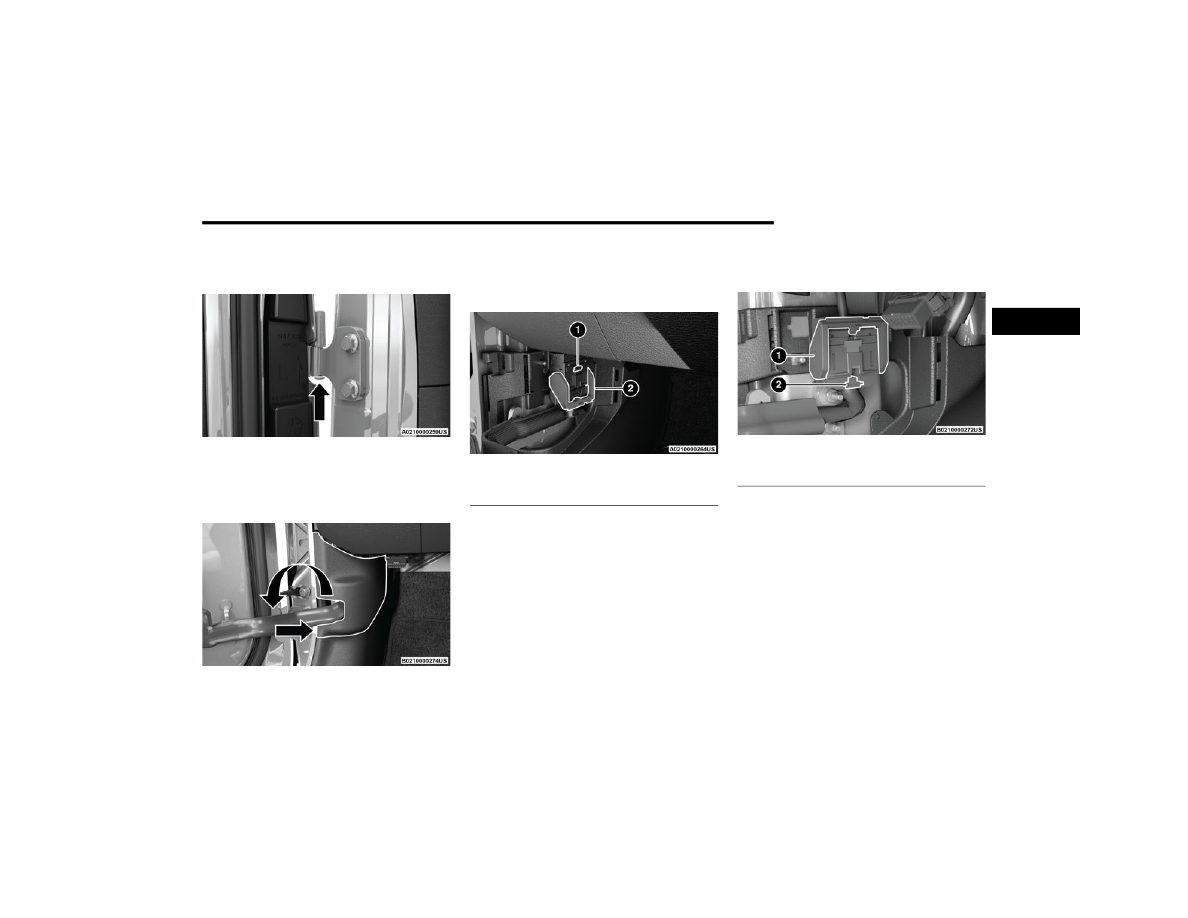
Hinge Pin Screw

3. Remove the plastic wiring access door under the 

instrument panel by sliding the plastic panel along 

the door frame toward the seats until the tabs are 

detached.

Wiring Access Door

NOTE:

Do not force open; this will break the plastic cover.
4. Pull up on the red locking tab to unlock the wiring 

harness.

Closed Wiring Harness

5. Push and hold down the black security tab under the 

wiring harness, and lift the harness lever into the 

open position.

Open Wiring Harness

6. With the wiring harness open, pull straight downward 

on the wiring connector to unplug. Store the wiring 

connector in the lower door basket.

1 – Red Locking Tab
2 – Wiring Harness Lever

1 – Wiring Harness Lever (Open Position)
2 – Black Security Tab

2

26

GETTING TO KNOW YOUR VEHICLE


7. With the door in the open position, remove the check 

bolt from the door check attachment on the bodyside 

(using a #T40 Torx head driver).

NOTE:

Keep the check arm in the extended position for easier 

reinstallation. See note below if the check arm gets 

pushed into the door while the door is off.

Door Check Arm

8. With the door open, lift the door with the help of 

another person, to clear the hinge pins from their 

hinges and remove the door.

To Install The Front Doors
1. Locate the upper and lower hinge pins on the door, 

and lower them into the body hinges on the vehicle.

NOTE:

The upper hinge pin is longer, which can be used to assist 

in guiding the door into place during installation.

Hinge Pin Locations

2. With the door in the open position, align the door 

check bracket with the hole on the bodyside. Insert 

the check screw and tighten using a #40 Torx head 

driver to 19.9 ft· lb (27.0 N·m).

NOTE:

If the check arm is stuck inside the door, follow these 

instructions to install the check arm: 
a. Insert the check arm screw into the check arm bracket. 

Ensure the screw is in the correct orientation.

b. Slowly pull on the screw to draw the check arm out until 

you encounter increased resistance. Do not attempt to 

pull the check arm all the way out.

c. While sitting inside the vehicle, hold the door partially 

closed and insert the screw into the hole on the body.

d. Using your fingers, turn the screw clockwise at least two 

full turns. Gently pull on the screw to ensure it is secure.

e. Using the door handle, slowly push the door open. The 

check arm will be pulled out of the door. You may hear 

the check arm pop against the screw.

f. Fully tighten the screw as instructed.

3. Insert the upper and lower hinge pin screws into the 

body hinges. Tighten the screws using a #T50 Torx 

head driver to 3.8 ft· lb / 5.2 N·m.

WARNING!

To avoid personal injury be sure to keep your arms, 

hands, fingers and all objects clear of the check arm 

area during the removal and installation procedures.

CAUTION!

Do not close the door before reattaching the door 

check to the body. Damage may occur to the door 

check.

Do not overtighten Torx fasteners, damage to the 

vehicle’s parts will occur.

Hinge pins can break if overtightened during door 

install (Max Torque: 6.0 ft· lb/8.1 N·m).

GETTING TO KNOW YOUR VEHICLE

27

Replacing The Wiring Connector Into The Wiring Harness
To reinstall the wiring connector on the vehicle’s door into 

the harness just inside the vehicle, proceed as follows:

NOTE:

Make sure there is plenty of slack on the wiring connector 

during installation. Close the door slightly to provide more 

slack if needed.
1. With light finger pressure, seat the wiring connector 

straight into the wiring harness until the wiring 

harness lever starts to lower with the latching pin.

Connecting The Wiring Harness

2. After the harness lever has started to move with the 

pressure of seating the wiring connector, continue by 

lowering the wiring harness lever to the fully closed 

position.

Fully Closed Position

3. Push the red locking tab downward to lock into place.
4. Attach the cloth strap of the door onto the metal hook 

just inside the vehicle.

Cloth Strap Attachment

5. Replace wiring access doors.

R

EAR

 D

OOR

 R

EMOVAL

(F

OUR

-D

OOR

 M

ODELS

1 — Seat Connector Straight Into Harness
2 — Wiring Harness Lever Starts To Lower

CAUTION!

Failure to correctly reconnect the wiring connector into 

the harness will result in damage that is not covered by 

the New Vehicle Warranty.

1 — Metal Hook
2 — Cloth Strap

WARNING!

Do not drive your vehicle on public roads with the doors 

removed as you will lose the protection they can 

provide. This procedure is furnished for use during 

off-road operation only. Failure to follow this warning 

can result in death or serious personal injury.

2

28

GETTING TO KNOW YOUR VEHICLE


Door Removal Warning Label

NOTE:

Doors are heavy; use caution when removing them.

Hinge pin can break if overtightened during door rein

-

stall (Max Torque: 7.5 ft· lb / 10 N·m). For off-road 

driving tips, see  

Ú

page 178.

To remove the rear doors, proceed as follows:
1. Roll down the glass window to prevent any damage.
2. Remove the hinge pin screws from the upper and 

lower outside hinges (using a #T50 Torx head driver).

NOTE:

The hinge pin screws and nuts can be stowed in the rear 

cargo tray located under the rear load floor.

Hinge Pin Screw

3. Slide the front seat(s) fully forward.
4. Pry open and remove the plastic wiring access door 

from the bottom of the B-pillar. 

Wiring Access Door

5. Unplug the wiring connector.

NOTE:

Squeeze the tab on the base of the wiring harness. This 

will unlock the connector tab, allowing the wiring 

connector to be unplugged.

Wiring Connector

WARNING!

All occupants must wear seat belts during off-road 

operation with doors removed. For off-road driving 

tips, see  

Ú

page 178.

Do not store detached doors inside of the vehicle, as 

they may fly around and cause personal injury or 

death in the event of a sudden stop, rough terrain, or 

a collision.

GETTING TO KNOW YOUR VEHICLE

29

6. With the door in the open position, remove the check 

bolt from the door check attachment on the body 

(using a #T40 Torx head driver).

NOTE:

Keep the check arm in the extended position for easier 

reinstallation.

Door Check Arm

7. With the door open, lift the door with the help of 

another person, to clear the hinge pins from their 

hinges and remove the door.

To reinstall the door(s), perform the previous steps in the 

reverse order.

NOTE:

The upper hinge has a longer pin, which can be used to 

assist in guiding the door into place when reinstalling.

D

OOR

 O

FF

 M

IRROR

 K

IT

 — I

F

 E

QUIPPED

If equipped with the Door Off Mirror Kit, exterior rearview 

mirrors can be installed on to the upper body door hinges 

after the front doors have been removed.

Use this QR code to access your digital 

experience.

Door Off Mirror

To install the Door Off Mirrors, proceed as follows:
1. Remove both front doors  

Ú

page 24.

2. Remove the cowl bolt closest to the door opening 

using a #40 Torx head driver, and store in a safe 

location.

Cowl Bolt Location

WARNING!

All occupants must wear seat belts during off-road 

operation with doors removed. For off-road driving 

tips, see  

Ú

page 178.

Do not store detached doors inside of the vehicle, as 

they may fly around and cause personal injury or 

death in the event of a sudden stop, rough terrain, or 

a collision.

2

30

GETTING TO KNOW YOUR VEHICLE


3. Push the mirror bracket forward onto the A-pillar, 

making sure to align the bottom of the bracket with 

the upper door hinge, and the hole from the removed 

cowl bolt.

Push Bracket Onto A-pillar

4. Place the bracket bushing behind the mirror bracket 

(over the cowl bolt hole), then insert the bracket bolt 

into the mirror bracket, through the bracket bushing.

Attaching Mirror Bracket To The Vehicle

5. Insert the hinge shoulder bolt through the bottom of 

the upper door hinge up into the mirror bracket, then 

rotate the bracket knob toward the rear of the vehicle 

to secure the mirror bracket to the A-pillar.

Attaching Mirror Bracket To The Vehicle

6. Tighten both the bracket bolt and the hinge shoulder 

bolt with a #40 Torx head driver. Recommended 

torque specification for the bracket bolt is 6 ft-lb 

(8 N·m), and 7.5 ft-lb (10 N·m) for the hinge shoulder 

bolt.

1 — Bracket Bushing
2 — Bracket Bolt

1 — Bracket Knob
2 — Hinge Shoulder Bolt

GETTING TO KNOW YOUR VEHICLE

31

7. Lower the mirror assembly onto the mirror bracket.

Lower Mirror Assembly Onto Bracket

8. Insert the three mirror screws into the mirror 

assembly, and tighten into the mirror bracket using a 

#30 Torx head driver. Recommended torque specifi

-

cation for the mirror screws is 4 ft-lb (5.5 N·m).

Mirror Screw Locations

9. Repeat the steps on the other side of the vehicle.

NOTE:

If this kit is being installed with the optional lamp bracket, 

the bracket bushing from step 4 is not needed. Use the 

spacer from the lamp bracket.

H

ALF

-D

OOR

 I

NSTALLATION

 — 

I

F

 E

QUIPPED

If applicable, refer to the “Hybrid Supplement” for 

additional information.

Use this QR code to access your digital 

experience.
This vehicle may be equipped with 

half-doors. To install the half-doors in 

the vehicle, follow the instruction sheet 

packaged in the box the doors were 

received in. Replacement parts may be 

purchased through Mopar® Service.
To install the front or rear half-doors, proceed as follows:
1. Remove the full doors from the vehicle. For front 

door removal, see  

Ú

page 24. For rear door removal, 

see  

Ú

page 27.

2. Locate the upper and lower hinge pins on the lower 

half-door, and lower them into the body hinges on the 

vehicle.

NOTE:

The upper hinge pin is longer, which can be used to assist 

in guiding the door into place during installation.

Lower Half-Door Hinge Pins

CAUTION!

Do not run half-doors through an automatic car 

wash. This may result in scratches and wax buildup 

on the windows.

Careless handling and storage of the half-doors may 

damage the seals resulting in water leaks into the 

interior of the vehicle.

The upper half-doors must be positioned properly to 

ensure sealing. Improper installation can cause 

water leaks into the interior of the vehicle.

Store the zipper pulls of the upper half-door windows 

at the upper B-pillar area for both front and rear 

doors to avoid damage to the windows when not in 

use.

Do not attempt to operate the half-door zipper in 

temperatures of 41°F (5°C) or below. Damage to the 

window may occur.

2

32

GETTING TO KNOW YOUR VEHICLE


3. Insert the upper and lower hinge pin screws into the 

body hinges. Tighten the screws using a #T50 Torx 

head driver to 3.8 ft· lb / 5.2 N·m.

4. Attach the cloth strap of the lower half-door to the 

metal hook just inside the vehicle.

Cloth Strap Attachment

5. Connect the wiring harness on the lower half-door to 

the connection just inside the vehicle.

NOTE:

For front doors, make sure the wiring harness is closed 

completely. 

Front Door Wiring Harness

6. Replace wiring access doors.
7. When the half-doors are shipped with the vehicle, the 

lower half-doors will have plugs in the post holes that 

must be removed prior to upper half-door installation. 

To remove these plugs, proceed as follows:
a. Locate the service hole in the center of each plug 

of the lower half-door (two on each front and rear 

door).

b. Place a tool (hook tool or trim stick is recom

-

mended) in the service hole.

Place Tool Into Service Hole Of Plug To Remove

c. Using the tool, slowly pull upwards from the center 

of the plug to remove.

8. Making sure the window on the upper half-door is 

completely zipped closed, insert the upper half-door 

into the lower half-door by placing the posts into the 

post holes.

Lower The Upper Half-Door Into Post Holes

CAUTION!

Do not close the door before reattaching the door 

check to the body. Damage may occur to the door 

check.

Do not overtighten Torx fasteners, damage to the 

vehicle’s parts will occur.

Hinge pins can break if overtightened during door 

install (Max Torque: 6.0 ft· lb/8.1 N·m).

1 — Metal Hook
2 — Cloth Strap

1 — Open Wiring Harness
2 — Closed Wiring Harness

GETTING TO KNOW YOUR VEHICLE

33

9. Push down firmly on the inside of the upper half-door 

until it is fully seated in the lower half.

Push Down To Fully Seat Upper Half-Door

Door Latch Alignment

Check Door Latch And Striker Alignment

NOTE:

Only adjust the door to fit correctly against the striker. DO 

NOT adjust the striker, as this could affect the positioning 

of the full door.
If the door does not center align between the latch and the 

striker, proceed as follows:
1. Loosen (do not remove) the four bolts on the door 

hinges using the provided #T50 Torx head driver.

Hinge Bolt Locations

2. With the bolts loose, hold the door in the almost 

closed position, and check that the latch and striker 

align.

3. With the latch and striker aligned, proceed to close 

the door softly and tighten the hinge bolts to 

20.3 ft· lb / 27.5 N·m (Max Torque: 27.3 ft· lb / 

37 N·m).

CAUTION!

Upon first installation of the half-doors, slowly set the 

door almost to the closing position and check how the 

door latch aligns with the body striker. Touch condition 

between these components can result in damage to 

both the door and the striker.

2

34

GETTING TO KNOW YOUR VEHICLE


Lower Door Adjustment

If the door does not latch properly after installation, if 

there is interference between the panels, or if a 

non-uniform gap around the door is observed when the 

door is closed (example: door position appears to be low 

and too far rearward), the position of the door on its hinges 

may need to be adjusted. To do this, proceed as follows:
1. Loosen (do not remove) the four bolts on the door 

hinges using the provided #T50 Torx head driver.

Hinge Bolt Locations

NOTE:

Do not adjust the body mounted hinges, or any part of the 

door latch, as modifications to these parts will affect 

installation of the full door.
2. With the bolts loose, the door can be moved forward 

by pushing the door handle toward the front of the 

vehicle, and/or upward by grabbing the door handle 

and lifting towards the roof.

3. Once the gaps between the door and vehicle body are 

uniform around the entire door, tighten the door 

hinge bolts to 20.3 ft· lb / 27.5 N·m (Max Torque: 

27.3 ft· lb / 37 N·m).

Upper Door Adjustment
After installation of the half-doors, if water leaks or wind 

noise is observed, the seal of the upper half-door to the 

door opening may need to be adjusted.
To determine if the upper half-door needs to be adjusted, 

proceed as follows:
1. Determine which door is affected.
2. Open the affected door and hold a dollar-size piece of 

paper along the top of the door opening against the 

vehicle near where the leak/noise was observed. 

Make sure half of the paper is above the area where 

the door seal contacts the door opening, while the 

other half is below.

3. Close the door on the paper, then pull the paper 

upward. If the paper moves with little to no effort, the 

upper half-door will need to be adjusted in that area 

to increase seal compression.

Performing A Paper Test

There is another optional test that can be performed using 

a flashlight and the help of another person.
One person should be inside the vehicle, and move the 

flashlight around the periphery of the door seal, shining 

outward. The other person should stand outside of the 

vehicle and check for light passing by the seal. If light is 

seen through the seal area, the door will need to be 

adjusted.

CAUTION!

Upon first installation of the half-doors, slowly close 

each door to check for body contact. Improper setting of 

the door hinges can cause extreme non-uniform 

conditions, and result in damage to the body around 

the door.

GETTING TO KNOW YOUR VEHICLE

35

To adjust the seal compression, proceed as follows:
1. Open the door and lift the upper half-door up and 

away from the lower half. Lay the upper half-door on 

a clean, dry surface.

2. Using an 8 mm open-end wrench (not provided), 

loosen the nut located inside the bottom of the upper 

half-door post, closest to where the “paper test” 

detected a gap.

Nut Location Inside Bottom Of Post

3. Using a 3 mm Allen wrench (not provided), rotate the 

screw on the side of the post counterclockwise (while 

holding the wrench on the loosened bolt) to increase 

the seal compression. If needed, rotate clockwise to 

reduce seal compression.

Rotate Screw For Seal Compression

4. Tighten the nut inside the bottom of the post using 

the wrench and make sure the screw head is flush to 

the post. Reinstall the upper half-door.

Screw Head Flush To Post

5. Close the door and repeat the “paper test”. Repeat 

the adjustment procedure if needed.

6. If needed, add the provided shim to a lower half-door 

pocket to seal the upper half-door to the roof:
a. Lift upper half-door up and away from lower half.
b. Clean the bottom of the door pocket.

Remove Upper Half-Door & Clean Bottom Of Door Pocket

c. Slide the shim onto a pencil or similar tool.
d. Remove the paper backing from the adhesive side 

of the shim and place the shim with pencil into the 

pocket.

e. Press the shim firmly to the bottom of the pocket, 

and remove the pencil once the shim is firmly in 

place.

1 — 3 mm Allen Wrench
2 — 8 mm Open-End Wrench

2

36

GETTING TO KNOW YOUR VEHICLE


Press Shim Firmly Into Bottom Of Pocket

f. Replace upper half-door.

NOTE:

If the compression is increased too much on the front 

upper corner of the rear doors, deformation of the seal will 

occur.
Half-Door Removal
To remove the half-doors, repeat the installation steps in 

reverse order.

NOTE:

When removing the upper half-doors, push upward firmly 

on the middle of the upper half-door until the posts detach 

from the lower half. 

Push Upward On Middle Of Upper Half Door To Remove

STEERING WHEEL

T

ILT

/T

ELESCOPING

 S

TEERING

 C

OLUMN


This feature allows you to tilt the steering column upward 

or downward. It also allows you to lengthen or shorten the 

steering column. The tilt/telescoping lever is located on 

the steering column.

Tilt/Telescoping Steering Column Lever

To unlock the steering column, push the control handle 

downward (toward the floor). To tilt the steering column, 

move the steering wheel upward or downward as desired. 

To lengthen or shorten the steering column, pull the 

steering wheel outward or push it inward as desired. To 

lock the steering column in position, push the control 

handle upward until fully engaged.

1 — Remove Paper Backing From Shim
2 — Slide Pencil through Hole In Shim
3 — Press Pencil With Shim Into Pocket

WARNING!

Do not adjust the steering column while driving. 

Adjusting the steering column while driving or driving 

with the steering column unlocked, could cause the 

driver to lose control of the vehicle. Failure to follow this 

warning may result in serious injury or death.

GETTING TO KNOW YOUR VEHICLE

37

(Continued)

H

EATED

 S

TEERING

 W

HEEL

 — 

I

F

 E

QUIPPED


The steering wheel contains a heating element 

that helps warm your hands in cold weather. 

The heated steering wheel has only one 

temperature setting. Once the heated steering 

wheel has been turned on, it will stay on until the operator 

turns it off. The heated steering wheel may not turn on 

when it is already warm.
The heated steering wheel control button is located within 

the Climate or Comfort screen of the touchscreen.

Press the heated steering wheel button once to turn 

the heating element on.

Press the heated steering wheel button a second time 

to turn the heating element off.

NOTE:

The engine must be running for the heated steering wheel 

to operate.
For information on use with the Remote Start system, see  

Ú

page 18.

SEATS    

Seats are a part of the Occupant Restraint system of the 

vehicle.

M

ANUAL

 A

DJUSTMENT

 F

RONT

 S

EATS

Manual Front Seat Forward/Rearward 

Adjustment

The seat can be adjusted forward or rearward by using a 

bar located by the front of the seat cushion, near the floor. 

While sitting in the seat, lift up on the bar located under 

the seat cushion and move the seat forward or rearward. 

Release the bar once you have reached the desired 

position. Then, using body pressure, move forward and 

rearward on the seat to be sure that the seat adjusters 

have latched.

Adjustment Bar Location

WARNING!

Persons who are unable to feel pain to the skin 

because of advanced age, chronic illness, diabetes, 

spinal cord injury, medication, alcohol use, exhaus

-

tion, or other physical conditions must exercise care 

when using the steering wheel heater. It may cause 

burns even at low temperatures, especially if used 

for long periods.

Do not place anything on the steering wheel that 

insulates against heat, such as a blanket or steering 

wheel covers of any type and material. This may 

cause the steering wheel heater to overheat.

WARNING!

It is dangerous to ride in a cargo area, inside or 

outside of a vehicle. In a collision, people riding in 

these areas are more likely to be seriously injured or 

killed.

Do not allow people to ride in any area of your vehicle 

that is not equipped with seats and seat belts. In a 

collision, people riding in these areas are more likely 

to be seriously injured or killed.

Be sure everyone in your vehicle is in a seat and 

using a seat belt properly.

WARNING!

WARNING!

Adjusting a seat while driving may be dangerous. 

Moving a seat while driving could result in loss of 

control which could cause a collision and serious 

injury or death.

Seats should be adjusted before fastening the seat 

belts and while the vehicle is parked. Serious injury 

or death could result from a poorly adjusted seat 

belt.

2

38

GETTING TO KNOW YOUR VEHICLE


Manual Seat Height Adjustment

The driver's seat height can be raised or lowered by using 

the ratcheting handle, located on the outboard side of the 

seat. Pull upward on the handle to raise the seat, push 

downward on the handle to lower the seat. Several strokes 

may be necessary to achieve the desired position.

Seat Height Adjustment

Manual Front Seat Recline Adjustment

To recline the seat, pull on the recline strap and lean 

forward or backward, depending on the direction you 

would like the seatback to move. Release the strap when 

the desired position is reached and the seatback will lock 

into place.

Recline Strap

Lumbar Support

The lumbar control knob is located on the outboard side of 

the front driver seat. Rotate the control forward to 

increase and rearward to decrease the desired amount of 

lumbar support.

Lumbar Control Knob

Front Passenger Easy Entry Seat — Two 

Door Models

Pull upward on the easy entry lever located on the 

outboard side of the seatback, and slide the entire seat 

forward.

Easy Entry Lever

WARNING!

Do not ride with the seatback reclined so that the 

shoulder belt is no longer resting against your chest. In 

a collision you could slide under the seat belt, which 

could result in serious injury or death.

GETTING TO KNOW YOUR VEHICLE

39

(Continued)

To return the seat to a sitting position, fold the seatback 

upright until it locks and push the seat rearward until the 

track locks.

NOTE:

The front passenger seats have a track memory, which 

returns the seat to its original position.

The recline strap and easy entry lever should not be 

used during the automatic returning of the seat to its 

sitting position.

60/40 S

PLIT

 F

OLDING

 R

EAR

 S

EAT

 — 

F

OUR

 D

OOR

 M

ODELS

To provide additional storage area, each rear seat can be 

folded flat to allow for extended cargo space.

NOTE:

Be sure that the front seats are fully upright and posi

-

tioned forward. This will allow the rear seat to fold down 

easily.

The center head restraints must be in the lowest posi

-

tion to avoid contact with the center console when 

folding the seat.

To Fold Down The Rear Seat

There are two release levers located on each upper 

outboard side of the rear seat. The larger of the two 

release levers folds down the seat and the head restraint 

simultaneously. The smaller lever folds down the head 

restraint independently for improved visibility.
To fold the seat, lift upward on the large release lever and 

slowly fold down the seatback. The head restraint will fold 

automatically with the seat when this lever is pulled.

Seatback Release Lever

NOTE:

You may experience deformation in the seat cushion from 

the seat belt buckles if the seats are left folded for an 

extended period of time. This is normal. By simply 

unfolding the seats to the open position, the seat cushion 

will return to its normal shape over time.

To Raise The Rear Seat

Raise the seatback and lock it into place. Then, raise the 

head restraint until it locks into place. If interference from 

the cargo area prevents the seatback from fully locking, 

you will have difficulty returning the seat to its proper 

position.

F

OLD

 A

ND

 T

UMBLE

 R

EAR

 S

EAT

 —

T

WO

 D

OOR

 M

ODELS

NOTE:

Prior to folding the rear seat, it may be necessary to 

reposition the front seats.

Be sure that the front seats are fully upright and posi

-

tioned forward. This will allow the rear seat to fold down 

easily.

WARNING!

It is extremely dangerous to ride in a cargo area, 

inside or outside of a vehicle. In a collision, people 

riding in these areas are more likely to be seriously 

injured or killed.

Do not allow people to ride in any area of your vehicle 

that is not equipped with seats and seat belts.

Be sure everyone in your vehicle is in a seat and 

using a seat belt properly.

WARNING!

WARNING!

Be certain that the seatback is securely locked into 

position. If the seatback is not securely locked into 

position the seat will not provide the proper stability for 

child seats and/or passengers. An improperly latched 

seat could cause serious injury.

2

40

GETTING TO KNOW YOUR VEHICLE


Folding The Rear Seat
1. Lift the seatback release lever and fold the seatback 

forward.

Rear Seatback Release Lever

2. Slowly flip the entire seat forward.

Using The Retention Straps
1. There are two retention straps located on the back 

of the rear seat and two corresponding wire loops 

located on the back of each B-pillar. Open the 

hook-and-loop fastener on the strap and thread 

through the wire loop. Fold the hook-and-loop 

fastener over to keep the seat in the folded position. 

This should be done on both sides.

Rear Seat Tumble Position Retention Strap

2. To return the seat to its normal upright position, 

reverse these steps.

Removing The Rear Seat
1. Push down on the release bar on each side, and pull 

the seat out and away from the lower bracket.

Release Bar Location

2. Remove the seat from the vehicle.
3. To reinstall the rear seat, just reverse these steps.

NOTE:

Do not drive the vehicle without reattaching the rear seat 

latches.

WARNING!

It is extremely dangerous to ride in a cargo area, 

inside or outside of a vehicle. In a collision, people 

riding in these areas are more likely to be seriously 

injured or killed.

Do not allow people to ride in any area of your vehicle 

that is not equipped with seats and seat belts.

Be sure everyone in your vehicle is in a seat and 

using a seat belt properly.

In a collision, you or others in your vehicle could be 

injured if seats are not properly latched to their floor 

attachments. Always be sure that the seats are fully 

latched.


Content      ..      1      2      3      ..