Jeep Grand Cherokee (2023 year). Manual in english - page 5
 

  Index      Manuals     Jeep Grand Cherokee (2023 year). Manual in english


Search            copyright infringement  


Content      ..     3      4      5      6     ..


Jeep Grand Cherokee (2023 year). Manual in english - page 5


76

GETTING TO KNOW YOUR VEHICLE


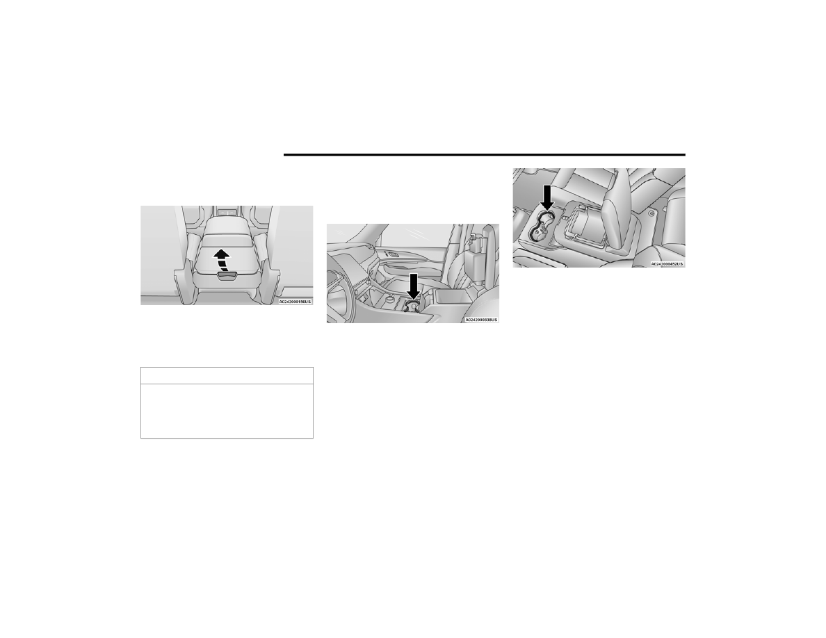
The storage compartment may also be lifted 

forward. Pull the paddle release lever located on 

the back of the console lid.

Rear Paddle Release Lever

When the second row seats are folded flat, lifting 

the console forward provides a flat load floor 

surface from the cargo area. There is also access 

to the storage compartment from the third row.

L

IGHTED

 C

UPHOLDERS

 — I

F

 E

QUIPPED

On some vehicles, the front cupholders are 

equipped with a light ring that illuminates the 

cupholders for the front passengers.

Light Ring In Front Cupholder

The rear cupholders may also be equipped with a 

light ring that illuminates the cupholders for the 

rear passengers. The light ring is controlled by the 

Dimmer Controls  

Ú

page 62.

Light Ring In Rear Cupholder (If Equipped)

S

UN

 S

CREENS

 — I

F

 E

QUIPPED

Sun screens are available for the second row 

seating windows. The screens store in the sill trim 

panels, and the tops of the windows are equipped 

with hooks that the sun screens attach to when 

pulled up.
Gently pull up on the tab to raise the sun screen. 

Continue pulling the sun screen until the tab is 

near the top of the window.
Once the screen is completely to the top of the 

window, extend the top bar of the sun screen over 

the two hooks attached to the top of the window.

CAUTION!

Remove any items stored in the console 

cupholders or devices with cords routing through 

upper storage area. Damage may occur to upper 

console lid and device cables when upper 

storage compartment is lifted forward.

GETTING TO KNOW YOUR VEHICLE

77

Sun Screen Extended

To lower the sun screen, gently lift the tab upward 

to disengage the hooks, and feed the screen back 

into the base sill.

USB/AUX C

ONTROL


This feature allows an external USB device to be 

plugged into one of the USB ports, located in the 

center stack of the instrument panel.
Plugging in a smartphone device to a USB port will 

activate Android Auto™ or Apple CarPlay® 

features, if equipped. For further information, refer 

to “Android Auto™” or “Apple CarPlay®” in the 

Uconnect Radio Instruction Manual.

NOTE:

Two devices can be plugged in at the same time, 

and both ports will provide charging capabilities. 

Only one port can transfer data to the system at a 

time.

For example, if a device is plugged into the Type A 

USB port and another device is plugged into the 

Type C USB port, a message will appear and allow 

you to select which device to use.
The following messages will appear when a 

non-phone device is plugged into the smaller and 

larger USB ports, and when a phone device is 

plugged into the smaller and larger USB ports:

“A new device is now connected. Previous 

connection was lost.”

“(Phone Name) now connected. Previous 

connection was lost.”

“Another device is in use through the same USB 

port. Please disconnect the first device to use 

the second device.”

Plugging in a phone or another USB device may 

cause the connection to a previous device to be 

lost.

Connecting AUX Or The External USB 

Device

Use a connection cable to connect an external USB 

device to the vehicle’s USB port, or use an auxiliary 

cable to connect a device to the vehicle’s AUX port. 

Both are located below the climate controls.

USB/AUX Ports

Once a device is connected to the USB port, it will 

begin charging and is ready for use with the 

system. Type C and Type A charge-only USB ports 

can be used at the same time but cannot be used 

simultaneously while playing media. When both 

Type C and Type A charge-only USB ports are in use 

they will be charged at a reduced rate.

NOTE:

If the device’s battery completely discharges, it 

may not communicate with the Uconnect system 

until a minimum charge is attained. Leaving the 

device connected to the USB port may charge it to 

the required level.

1 — USB C Port
2 — USB A Port (Standard USB)
3 — AUX Port

2

78

GETTING TO KNOW YOUR VEHICLE


Using This Feature

By using a USB cable to connect an external 

device: 

The device can be played on the vehicle’s sound 

system, and provides the artist, track title, and 

album information on the radio display.

NOTE:

Depending on track configuration, track infor

-

mation may not be present on the radio display.

The device can be controlled using the radio 

buttons to play and browse the contents of the 

device.

The audio device battery charges when plugged 

into the USB port.

By using an auxiliary cable to connect an external 

device: 

The audio device can be played on the vehicle’s 

sound system. The Uconnect system will not 

display information related to the artist, track 

title, and album information.

NOTE:

When using the AUX port, the external device 

cannot be controlled using the radio buttons. The 

device will not charge.
For further information, refer to the Uconnect 

Radio Instruction Manual.

Second And Third Row USB Ports   

The second row USB ports can be used to charge 

an external device.

Center Console Rear USB Ports

In the third row, a set of two USB ports can be used 

to charge a device. These ports are charge only.

Third Row USB Ports

NOTE:

Charge unsupported devices with the Charge Only 

USB ports. If an unsupported device is plugged into 

a Media USB port, a message will display on the 

touchscreen that the device is not supported by 

the system.

E

LECTRICAL

 P

OWER

 O

UTLETS


Your vehicle is equipped with 12 Volt (13 Amp) 

power outlets that can be used to power cellular 

phones, small electronics and other low powered 

electrical accessories. The power outlets are 

labeled with either a “key” or a “battery” symbol to 

indicate how the outlet is powered. Power outlets 

labeled with a key symbol are powered when the 

1 — Charge Only Type C USB Port
2 — Charge Only Type A USB Port

GETTING TO KNOW YOUR VEHICLE

79

(Continued)

ignition switch is in the ON/RUN position, while the 

outlets labeled with a battery symbol are 

connected directly to the battery and powered at 

all times.

NOTE:

All accessories connected to the battery 

powered outlets should be removed or turned 

off when the vehicle is not in use to protect the 

battery against discharge.

Do not exceed the maximum power of 160 W 

(13 Amp) at 12 Volt. If the 160 W (13 Amp) 

power rating is exceeded the fuse protecting the 

system needs to be replaced.

Power outlets are designed for accessory plugs 

only. Do not insert any other object in the power 

outlets as this will damage the outlet and blow 

the fuse. Improper use of the power outlet can 

cause damage not covered by your New Vehicle 

Limited Warranty.

The front power outlet is located inside the storage 

area on the center stack of the instrument panel, 

below the climate controls.

Front Power Outlet

The rear cargo power outlet is located in the right 

rear cargo area when the vehicle is equipped with 

third row seating. When the vehicle is equipped 

with only two row seating, the cargo area outlet is 

located on the left side trim panel.

Rear Cargo Power Outlet (Third Row Seating)

NOTE:

The rear cargo power outlet can be changed from 

battery powered to powered by ignition in the ON/

RUN position by switching the cargo area power 

outlet fuse from F44B to F44A in the rear power 

distribution center  

Ú

page 352.

WARNING!

To avoid serious injury or death:

Only devices designed for use in this type of 

outlet should be inserted into any 12 Volt 

outlet.

Do not touch with wet hands.

Close the lid when not in use and while driving 

the vehicle.

If this outlet is mishandled, it may cause an 

electric shock and failure.

CAUTION!

Many accessories that can be plugged in draw 

power from the vehicle's battery, even when 

not in use (i.e., cellular phones, etc.). Eventu

-

ally, if plugged in long enough, the vehicle's 

battery will discharge sufficiently to degrade 

battery life and/or prevent the engine from 

starting.

2

80

GETTING TO KNOW YOUR VEHICLE


P

OWER

 I

NVERTER

 — I

F

 E

QUIPPED

There is a 115 Volt, 150 W inverter outlet located 

on the back of the center console to convert DC 

current to AC current. This outlet can power cellular 

phones, electronics and other low power devices 

requiring power up to 150 W. Certain video game 

consoles exceed this power limit, as will most 

power tools.

Power Inverter

The power inverter is designed with built-in 

overload protection. If the power rating of 150 W is 

exceeded, the power inverter automatically shuts 

down. Once the electrical device has been 

removed from the outlet the inverter should 

automatically reset. To avoid overloading the 

circuit, check the power ratings on electrical 

devices prior to using the inverter.

W

IRELESS

 C

HARGING

 P

AD

 — 

I

F

 E

QUIPPED


Wireless Charging Pad

Your vehicle may be equipped with a 15 W3 Amp 

Qi wireless charging pad located inside of the 

storage area below the climate controls. This 

charging pad is designed to wirelessly charge your 

Qi enabled mobile phone. Qi is a standard that 

allows wireless charging of your mobile phone.
Your mobile phone must be designed for Qi 

wireless charging. If the phone is not equipped 

with Qi wireless charging functionality, an 

aftermarket sleeve or a specialized back plate can 

be purchased from your mobile phone provider or 

a local electronics retailer. Please see your 

phone’s owner’s manual for further information.

Accessories that draw higher power (i.e., 

coolers, vacuum cleaners, lights, etc.) will 

degrade the battery even more quickly. Only 

use these intermittently and with greater 

caution.

After the use of high power draw accessories, 

or long periods of the vehicle not being started 

(with accessories still plugged in), the vehicle 

must be driven a sufficient length of time to 

allow the generator to recharge the vehicle's 

battery.

CAUTION!

WARNING!

To avoid serious injury or death:

Do not insert any objects into the receptacles.

Do not touch with wet hands.

Close the lid when not in use.

If this outlet is mishandled, it may cause an 

electric shock and failure.

GETTING TO KNOW YOUR VEHICLE

81

The wireless charging pad is equipped with an 

anti-slip mat to hold your mobile phone in place, 

and an LED indicator light.
LED Indicator Status:

No Light: Charging pad is idle or searching for a 

device.

Blue Light: Device is detected and is charging.

Red Light/Flashing: Internal error or foreign 

object is detected.

Important Notes Regarding This Vehicle’s Wireless 

Charging Pad:

All vehicle doors must be closed for the wireless 

charging pad to operate.

If the phone moves on the pad causing the red 

light to illuminate, the phone will have to be 

picked up and placed back on the charging pad 

to resume charging.

Wireless charging is not as fast as when the 

phone is connected to a wired charger.

The phone’s protective case must be removed 

when placed on the wireless charging pad.

iPhone® 12 (including iPod®) is equipped with 

software to protect the device from overheating. 

When the software is active, the rate of charge 

is slowed down to protect the device.

Phones must always be placed on the wireless 

charging pad within the outline shown on the 

pad so that its charging parts connect with the 

charging coils of the system. Movement of the 

phone during charging may prevent or slow the 

rate of charge.

Having multiple applications open on the phone 

while charging will reduce the charging effi

-

ciency, and may even shut down an application 

that is actively running (i.e. Apple CarPlay®). 

This may also cause the phone to overheat.

Wireless chargers may implement certain 

methods to prevent the phone from overheating 

during charging such as slowing down the rate 

of charge. In certain instances, the device may 

shut down for a brief period of time (when the 

device reaches a certain temperature). If this 

happens, it does not mean there is a fault with 

the wireless charing pad. This may just be a 

protective measure to prevent damage to the 

phone.

WINDOWS 

P

OWER

 W

INDOW

 C

ONTROLS

The power window controls, located on the driver's 

door trim panel, operate the window movement for 

all four power windows.
There is a single switch on the front passenger 

door and rear passenger doors which operates the 

windows for only that door.

Driver’s Door Power Window Switches

NOTE:

The power window switches remain active for up 

to 10 minutes after the ignition has been placed 

in the OFF position. Opening a vehicle front door 

will cancel this feature.

CAUTION!

The key fob should not be placed on the 

charging pad or within 6 inches (15 cm) of it. 

Doing so can cause excessive heat buildup and 

damage to the fob. Placing the fob in close 

proximity of the charging pad blocks the fob from 

being detected by the vehicle and prevents the 

vehicle from starting.

2

82

GETTING TO KNOW YOUR VEHICLE


The window controls will operate only when the 

vehicle’s ignition is placed in the ON/RUN posi

-

tion.

The power windows may be operated from 

outside of the vehicle by using the key fob. For 

more information, see  

Ú

page 19.

Automatic Window Features

Both the driver and front passenger windows, and 

if equipped, both rear windows, may have 

Auto-Down and Auto-Up operations.
Auto-Down Feature
For windows equipped with the AUTO feature, push 

the window switch down to the second detent, 

release, and the window will go down 

automatically.

To stop the window from going all the way down 

during the Auto-Down operation, pull up or push 

down on the switch briefly.
Auto-Up Feature With Anti-Pinch Protection
For windows equipped with the AUTO feature, lift 

the window switch up to the second detent, and 

release; the window will go up automatically.
To stop the window from going all the way up 

during the Auto-Up operation, push down on the 

switch briefly.
To close the window part way, lift the window 

switch briefly and release it when you want the 

window to stop.
For vehicles equipped with anti-pinch protection, if 

the window runs into any obstacle during 

auto-closure, it will reverse direction and then go 

back down. Remove the obstacle and use the 

window switch again to close the window.

NOTE:

Any impact due to rough road conditions may 

trigger the auto-reverse function unexpectedly 

during auto-closure. If this happens, pull the switch 

lightly and hold to close the window manually.

Reset Auto-Up 

Should the Auto-Up feature stop working, the 

window may need to be reset. To reset Auto-Up:
Front Doors
1. Pull the window switch up to close the window 

completely and continue to hold the switch up 

for an additional two seconds after the 

window is closed.

Rear Doors
1. Pull the window switch up to close the window 

completely and continue to hold the switch up 

for an additional two seconds after the 

window is closed.

2. Release the window switch, and within five 

seconds, pull the window switch up again for 

an additional two seconds.

WARNING!

Never leave children unattended in a vehicle, 

and do not let children play with power windows. 

Do not leave the key fob in or near the vehicle, or 

in a location accessible to children, and do not 

leave the Keyless Enter ‘n Go™ Ignition in the 

ON/RUN position. Occupants, particularly 

unattended children, can become entrapped by 

the windows while operating the power window 

switches. Such entrapment may result in serious 

injury or death.

WARNING!

There is no anti-pinch protection when the 

window is almost closed. To avoid personal 

injury be sure to clear your arms, hands, fingers 

and all objects from the window path before 

closing.

GETTING TO KNOW YOUR VEHICLE

83

Window Lockout Switch

The window lockout switch on the driver's door trim 

panel allows you to disable the window controls on 

the rear passenger doors. To disable the window 

controls, push and release the window lockout 

button (the indicator light on the button will turn 

on). To enable the window controls, push and 

release the window lockout button again (the 

indicator light on the button will turn off).

Power Window Lockout Switch

W

IND

 B

UFFETING


Wind buffeting can be described as the perception 

of pressure on the ears or a helicopter-type sound 

in the ears. Your vehicle may exhibit wind buffeting 

with the windows down, or the sunroof (if 

equipped) in certain open or partially open 

positions. This is a normal occurrence and can be 

minimized. If the buffeting occurs with the rear 

windows open, open the front and rear windows 

together to minimize the buffeting. If the buffeting 

occurs with the sunroof open, adjust the sunroof 

opening to minimize the buffeting or open any 

window.

POWER SUNROOF — IF EQUIPPED 

S

INGLE

 P

ANE

 P

OWER

 S

UNROOF

 — 

I

F

 E

QUIPPED


The power sunroof switches are located on the 

overhead console between the courtesy/reading 

lights.

Power Sunroof Switches

1 — Opening/Closing Sunroof
2 — Venting Sunroof

WARNING!

Never leave children unattended in a vehicle, 

or with access to an unlocked vehicle. Never 

leave the key fob in or near the vehicle, or in a 

location accessible to children. Do not leave 

the Keyless Enter ‘n Go™ Ignition in the ON/

RUN position. Occupants, particularly unat

-

tended children, can become entrapped by 

the power sunroof while operating the power 

sunroof switch. Such entrapment may result 

in serious injury or death.

In a collision, there is a greater risk of being 

thrown from a vehicle with an open sunroof. 

You could also be seriously injured or killed. 

Always fasten your seat belt properly and 

make sure all passengers are also properly 

secured.

Do not allow small children to operate the 

sunroof. Never allow your fingers, other body 

parts, or any object, to project through the 

sunroof opening. Injury may result.

2

84

GETTING TO KNOW YOUR VEHICLE


Opening And Closing The Sunroof

Express Open/Close
To open the sunroof, push OPEN on the sunroof 

switch and release it within one-half second and 

the sunroof will open automatically from any 

position.
To close the sunroof, push CLOSE on the sunroof 

switch and release it within one-half second and 

the sunroof will close automatically from any 

position.
During Express Open or Express Close operation, 

any other actuation of the sunroof switch will stop 

the sunroof.
Manual Open/Close
To open the sunroof, push and hold OPEN on the 

sunroof switch.
To close the sunroof, push and hold CLOSE on the 

sunroof switch.
Any release of the switch during open or close 

operation will stop the sunroof movement in a 

partially open position. The sunroof will remain in a 

partially opened position until the switch is 

operated and held again.

Express Venting The Sunroof
To vent the sunroof, push TILT on the vent switch 

and release within one half second. The sunroof 

will open to the vent position regardless of its initial 

position. During Express Vent operation, any other 

actuation of the switch will stop the sunroof.

NOTE:

If the sunshade is in the closed position when 

Express/Manual Open or Vent operation is 

initiated, the sunshade will automatically open 

with the sunroof glass.

Pinch Protect Feature

This feature will detect an obstruction in the 

opening of the sunroof during Express Close 

operation. If an obstruction in the path of the 

sunroof is detected, the sunroof will automatically 

retract. Remove the obstruction if this occurs.

NOTE:

If three consecutive sunroof close attempts result 

in Pinch Protect reversals, Pinch Protect will 

disable and the sunroof must be closed in Manual 

Mode.

Sunshade Operation

The sunshade can be opened manually. However, 

the sunshade will open automatically as the 

sunroof opens.

NOTE:

The sunshade cannot be closed if the sunroof is 

open.

Ignition Off Operation

The power sunroof switch will remain active for up 

to approximately 10 minutes after the ignition 

switch is placed in the OFF position. Opening either 

front door will cancel this feature.

NOTE:

Ignition Off timing is programmable through the 

Uconnect system  

Ú

page 204.

Sunroof Maintenance

Use only a non-abrasive cleaner and a soft cloth to 

clean the glass panel. Periodically check for and 

clear out any debris that may have collected in the 

tracks.

GETTING TO KNOW YOUR VEHICLE

85

D

UAL

 P

ANE

 P

OWER

 S

UNROOF

 —

I

F

 E

QUIPPED


The power sunroof switches are located on the 

overhead console between the courtesy/reading 

lights.

Power Sunroof Switches

Opening And Closing The Sunroof

The sunroof has two programmed automatic stops 

for the sunroof open position: a comfort stop 

position and a full open position. The comfort stop 

position will minimize wind buffeting in the interior.

Express Open/Close
To open the sunroof, push OPEN on the sunroof 

switch and release it within one-half second. The 

sunroof will open to the comfort stop position and 

stop automatically. Push and release OPEN again 

to continue to the full open position.
To close the sunroof, push CLOSE on the sunroof 

switch and release it within one-half second. The 

sunroof will close automatically from any position.
During Express Open or Express Close operation, 

any other actuation of the sunroof switch will stop 

the sunroof.
Manual Open/Close
To open the sunroof, push and hold OPEN on the 

sunroof switch. The sunroof will open to the 

comfort stop position, then automatically stop. 

Release the switch then push and hold again to 

continue to the full open position.
To close the sunroof, push and hold CLOSE on the 

sunroof switch.
Any release of the switch during open or close 

operation will stop the sunroof movement in a 

partially open position.

1 — Opening/Closing Sunroof
2 — Venting Sunroof
3 — Opening/Closing Sunshade

WARNING!

Never leave children unattended in a vehicle, 

or with access to an unlocked vehicle. Never 

leave the key fob in or near the vehicle, or in a 

location accessible to children. Do not leave 

the Keyless Enter ‘n Go™ Ignition in the ON/

RUN position. Occupants, particularly unat

-

tended children, can become entrapped by 

the power sunroof while operating the power 

sunroof switch. Such entrapment may result 

in serious injury or death.

In a collision, there is a greater risk of being 

thrown from a vehicle with an open sunroof. 

You could also be seriously injured or killed. 

Always fasten your seat belt properly and 

make sure all passengers are also properly 

secured.

Do not allow small children to operate the 

sunroof. Never allow your fingers, other body 

parts, or any object, to project through the 

sunroof opening. Injury may result.

2

86

GETTING TO KNOW YOUR VEHICLE


Express Venting The Sunroof
To vent the sunroof, push TILT on the vent switch 

and release within one half second. The sunroof 

will open to the vent position regardless of its initial 

position. During Express Vent operation, any other 

actuation of the switch will stop the sunroof.

NOTE:

If the sunshade is in the closed position when 

Express/Manual Open or Vent operation is 

initiated, the sunshade will automatically open to 

the half open position prior to the sunroof opening.

Opening And Closing The Power Sunshade

The sunshade has two programmed open 

positions: half open and full open positions. When 

operating the sunshade from the closed position, 

the sunshade will always stop at the half open 

position regardless of express or manual open 

operation. The switch must be pushed again to 

continue on to full open position.
If the sunroof is open or vented, the sunshade 

cannot be closed beyond the half open position. 

Pushing the sunshade close switch when the 

sunroof is open/vented and the sunshade is at half 

open position will first automatically close the 

sunroof prior to the sunshade closing.

Express Open/Close
To open the sunshade, push OPEN on the 

sunshade switch and release it within one-half 

second, the sunshade will open to the half open 

position and stop automatically. Push and release 

OPEN again to continue to open the sunshade to 

the full open position.
To close the sunshade, push CLOSE on the 

sunshade switch and release it within one-half 

second.
During Express Open or Express Close operation, 

any other actuation of the sunroof switches will 

stop the sunshade in a partially open position.
Manual Open/Close
To open the sunshade, push and hold OPEN on the 

sunshade switch, the sunshade will open to the 

half open position and stop automatically. Push 

and hold OPEN again to continue to open the 

sunshade to the full open position.
To close the sunshade, push and hold CLOSE on 

the sunshade switch.
Releasing the switch while the sunshade is in 

motion will stop the sunshade in a partially open 

position.

Pinch Protect Feature

This feature will detect an obstruction in the 

opening of the sunroof during Express Close 

operation. If an obstruction in the path of the 

sunroof is detected, the sunroof will automatically 

retract. Remove the obstruction if this occurs.

NOTE:

If three consecutive sunroof close attempts result 

in Pinch Protect reversals, Pinch Protect will 

disable and the sunroof must be closed in Manual 

Mode.

Ignition Off Operation

The power sunroof switch will remain active for up 

to approximately 10 minutes after the ignition 

switch is placed in the OFF position. Opening either 

front door will cancel this feature.

NOTE:

Ignition Off timing is programmable through the 

Uconnect system  

Ú

page 204.

Sunroof Maintenance

Use only a non-abrasive cleaner and a soft cloth to 

clean the glass panel. Periodically check for and 

clear out any debris that may have collected in the 

tracks.

GETTING TO KNOW YOUR VEHICLE

87

HOOD   

O

PENING

 T

HE

 H

OOD

To open the hood, two latches must be released.
1. Pull the release lever located at the bottom of 

the driver’s side of the instrument panel.

Hood Release

2. Reach under the hood from outside the 

vehicle, move the safety latch to the left and 

lift the hood.

Safety Latch Location

NOTE:

Vehicle must be at a stop and the gear selector 

must be in PARK.

While lifting the hood, use both hands.

Before lifting the hood, check that the wiper 

arms are not in motion and not in the lifted posi

-

tion.

C

LOSING

 T

HE

 H

OOD

In one continuous motion, pull down on the front 

edge of the hood with moderate force until the 

angle is below the crossover point (where the gas 

props are no longer resisting) and let the hood 

continue to fall closed from its own inertia.

WARNING!

Be sure the hood is fully latched before driving 

your vehicle. If the hood is not fully latched, it 

could open when the vehicle is in motion and 

block your vision. Failure to follow this warning 

could result in serious injury or death.

2

88

GETTING TO KNOW YOUR VEHICLE


LIFTGATE

T

O

 U

NLOCK

/O

PEN

 T

HE

 L

IFTGATE

The power liftgate may be opened by 

pushing the liftgate button on the key fob 

or by pushing the electronic liftgate 

release button.

Push the liftgate button on the key fob twice within 

five seconds to open the power liftgate. Once the 

liftgate is open, pushing the button twice within 

five seconds a second time will close the liftgate.

Liftgate Entry

NOTE:

When you push the electronic liftgate release button, 

either only the liftgate will unlock, or all the doors and 

the liftgate will unlock, depending on the selected 

setting in the Uconnect system  

Ú

page 204.

NOTE:

Use the power door lock switch on either front 

door trim panel or the key fob to lock and unlock 

the liftgate.

The driver's door lock cylinder will not lock or 

unlock the liftgate.

NOTE:

The liftgate can also be opened manually by 

pushing the electronic liftgate release button and 

pulling upward in one fluid motion.

T

O

 L

OCK

/C

LOSE

 T

HE

 L

IFTGATE

There are several different ways to close the 

liftgate: 

Manually (grab the liftgate closing handle and 

pull in a downward motion)

Key fob

Hands-free (if equipped)

Liftgate close button in the cargo area

With a valid Passive Entry key fob within 5 ft 

(1.5 m) of the liftgate, pushing the Passive Entry 

button located to the left of the electronic liftgate 

release button, will lock the vehicle only.
If the liftgate is fully open, the liftgate can be closed 

by pushing the liftgate close button located in the 

cargo area on the left rear trim panel, near the 

liftgate opening. If the liftgate is in motion, pushing 

the liftgate close button a second time will reverse 

the liftgate operation.

Liftgate Close Button

1 — Passive Entry Button
2 — Electronic Liftgate Release Button

WARNING!

Driving with the liftgate open can allow 

poisonous exhaust gases into your vehicle. You 

and your passengers could be injured by these 

fumes. Keep the liftgate closed when you are 

operating the vehicle.

GETTING TO KNOW YOUR VEHICLE

89

A

DJUSTABLE

 P

OWER

 L

IFTGATE

 H

EIGHT

The maximum height that the liftgate will open can 

be adjusted and saved so that the liftgate will only 

open to the desired height. To set a desired height, 

proceed as follows:
1. Open the liftgate fully, then manually pull 

down on the liftgate to the desired height.

2. Push and hold the liftgate close button, 

located on the left side trim panel inside the 

cargo area, for three seconds. An audible 

chime will be emitted to let you know the 

height has been saved.

To set the saved height setting to a new setting, 

proceed as follows:
1. Open the liftgate, then manually push the 

liftgate upward to its full open position.

2. Manually pull the liftgate down to the new 

desired height and hold the liftgate close 

button for three seconds until the audible 

chime is emitted.

Power Liftgate Malfunction Procedure:
1. In the event of a power malfunction to the 

liftgate, the liftgate can be released by 

accessing the service release feature in the 

latch. This can be done using a 3 mm 

diameter screwdriver.

Liftgate Service Release

2. From inside the gate, an eyelet can be seen. 

Place the screwdriver in the eyelet.

3. Rotate the screwdriver handle to actuate the 

lever and release the latch.

4. If liftgate is left open for an extended period of 

time, the liftgate may need to be closed 

manually to reset power liftgate functionality.

H

ANDS

-F

REE

 L

IFTGATE

 — I

F

 E

QUIPPED


Hands-Free Liftgate Activation Zone

To open or close the liftgate using hands-free 

activation, use a straight in and out kicking motion 

under the vehicle activation zone in the general 

location below the rear license plate. The activation 

zone is about 1.8 ft (0.5 m) from side to side. Do not 

move your foot sideways or in a sweeping motion or 

the sensors may not detect the motion.

NOTE:

The activation zone is the same for vehicles 

equipped with or without a trailer tow package.
When a valid kicking motion is completed, the 

liftgate will chime, the hazard lights will flash and 

the liftgate will open after approximately one 

second, or close after approximately three 

seconds. These settings can be enabled or 

disabled through Uconnect Settings  

Ú

page 204.

2

90

GETTING TO KNOW YOUR VEHICLE


NOTE:

Opening or closing the Hands-Free Liftgate 

requires a valid Passive Entry key fob within 5 ft 

(1.5 m) of the liftgate handle. If a valid Passive 

Entry key fob is not within 5 ft (1.5 m), the lift

-

gate will not respond to any kicks.

The Hands-Free Liftgate feature may be turned 

on or off through the Uconnect system  

Ú

page 204.

The Hands-Free Liftgate feature should be 

turned off during jacking, tire changing, manual 

car wash, and vehicle service.

The Hands-Free Liftgate feature can be acti

-

vated by any metallic object making a similar 

in-and-out motion under the rear fascia/

bumper, such as cleaning using a metal broom.

The Hands-Free Liftgate will only operate when 

the transmission is in PARK.

If anything obstructs the Hands-Free Liftgate 

while it is opening or closing, the liftgate will 

automatically reverse to the closed/open posi

-

tion, provided it meets sufficient resistance.

There are pinch sensors attached to the side of 

the liftgate opening. Light pressure anywhere 

along these strips will cause the liftgate to 

return to the open position.

If the power liftgate encounters multiple 

obstructions within the same cycle, the system 

will automatically stop. If this occurs, the liftgate 

must be operated manually.

The power liftgate will release, but not power 

open, in temperatures below −12°F (−24°C). 

Be sure to remove any buildup of snow or ice 

from the liftgate before opening the liftgate.

If the liftgate is left open for an extended period 

of time (approximately one hour), the liftgate 

may need to be closed manually to reset power 

liftgate functionality.

Gas props support the liftgate in the open position. 

However, because the gas pressure drops with 

temperature, it may be necessary to assist the 

props when opening the liftgate in cold weather.

NOTE:

Allow the power system to open the liftgate. 

Manually pushing or pulling the liftgate may 

activate the liftgate obstacle detection feature and 

stop the power operation or reverse its direction.

C

ARGO

 A

REA

 F

EATURES

Cargo Storage

The load floor is designed for a maximum load of 

300 lb (136 kg).
If equipped, there may be a removable storage bin 

located on the left side of the rear cargo area.

WARNING!

Driving with the liftgate open can allow 

poisonous exhaust gases into your vehicle. 

You and your passengers could be injured by 

these fumes. Keep the liftgate closed when 

you are operating the vehicle.

If you are required to drive with the liftgate 

open, make sure that all windows are closed, 

and the climate control blower switch is set at 

high speed. Do not use the recirculation 

mode.

WARNING!

During power operation, personal injury or cargo 

damage may occur. Ensure the liftgate travel 

path is clear. Make sure the liftgate is closed 

and latched before driving away.

GETTING TO KNOW YOUR VEHICLE

91

(Continued)

Additional storage can be found under the storage 

lid. To access the lower storage, lift the handle and 

raise the storage lid.

Lift Storage Lid Handle

Cargo Tie-Down Hooks 

The cargo tie-downs, located on the cargo area 

sides, should be used to safely secure loads when 

the vehicle is moving.

NOTE:

The cargo tie-downs are designed for a maximum 

load of 300 lb (136 kg).

Tie-Down Hooks (Vehicles With Third Row Seating)

Tie-Down Hooks (Vehicles Without Third Row Seating)

WARNING!

Cargo tie-downs are not safe anchors for a 

child seat tether strap. In a sudden stop or 

accident, a tie-down could pull loose and allow 

the child seat to come loose. A child could be 

badly injured. Use only the anchors provided 

for child seat tethers.

To help protect against personal injury, 

passengers should not be seated in the rear 

cargo area. The rear cargo space is intended 

for load carrying purposes only, not for 

passengers, who should sit in seats and use 

seat belts.

The weight and position of cargo and 

passengers can change the vehicle center of 

gravity and vehicle handling. To avoid loss of 

control resulting in personal injury, follow these 

guidelines for loading your vehicle:

Do not carry loads that exceed the load limits 

described on the label attached to the left 

door or left door center pillar.

Always place cargo evenly on the cargo floor. 

Put heavier objects as low and as far forward 

as possible.

2


Content      ..     3      4      5      6     ..