Jeep Patriot (2017 year). Instruction - part 8
 

  Index      Jeep     Jeep Patriot - instruction 2017 year in english


Search            


Content   ..  6  7  8  9   ..


Jeep Patriot (2017 year). Instruction - part 8


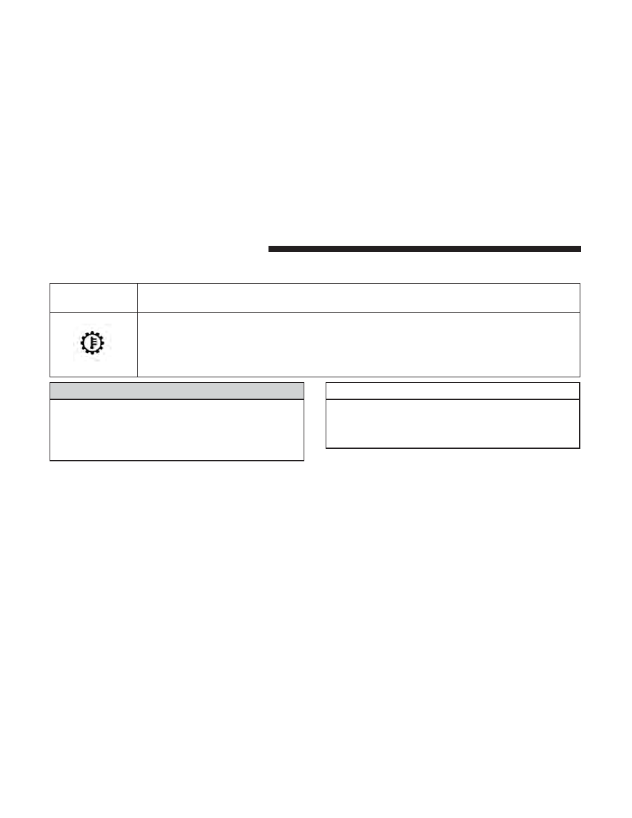
Transmission Temperature Indicator Light

Yellow Telltale

Light

What It Means

Transmission Temperature Indicator Light
This light indicates that the transmission fluid temperature is running hot. This may occur with
severe usage, such as trailer towing. If this light turns on, safely pull over and stop the vehicle.
Then, shift the transmission into NEUTRAL and run the engine at idle or faster until the light
turns off.

WARNING!

If you continue operating the vehicle when the Trans-
mission Temperature Warning Light is illuminated you
could cause the fluid to boil over, come in contact with
hot engine or exhaust components and cause a fire.

CAUTION!

Continuous driving with the Transmission Tempera-
ture Warning Light illuminated will eventually cause
severe transmission damage or transmission failure.

112

GETTING TO KNOW YOUR INSTRUMENT PANEL

Green Telltale Lights

Turn Signal Warning Lights

Green Tell-

tale Light

What It Means

Turn Signal Indicator Lights
The instrument cluster arrow will flash independently for the left or right turn signal as selected, as
well as the exterior turn signal lamp(s) (front and rear) as selected when the multifunction lever is
moved down (left) or up (right).

NOTE:

• A continuous chime will sound if the vehicle is driven more than 1 mile (1.6 km) with either turn

signal on.

• Check for an inoperative outside light bulb if either indicator flashes at a rapid rate.

Park/Headlight ON Indicator Light

Green Telltale

Light

What It Means

Park/Headlight ON Indicator Light
This indicator will illuminate when the park lights or headlights are turned on.

4

GETTING TO KNOW YOUR INSTRUMENT PANEL

113

Front Fog Indicator Light — If Equipped

Green Telltale

Light

What It Means

Front Fog Indicator Light
This indicator will illuminate when the front fog lights are on.

Blue Telltale Indicator Lights

High Beam Indicator Light

Blue Telltale

Light

What It Means

High Beam Indicator Light
This indicator shows that the high beam headlights are on. Push the multifunction control lever
away from you to switch the headlights to high beam. Pull the lever toward you to switch the
headlights back to low beam. Pull the lever toward you for a temporary high beam on,

⬙flash to

pass

⬙ scenario.

114

GETTING TO KNOW YOUR INSTRUMENT PANEL

White Telltale Lights

Cruise Control On Indicator Light

White Telltale

Light

What It Means

Cruise Control On Indicator Light
This indicator shows when the electronic speed control system is turned on.

Hill Decent Control (HDC) Indicator Light — If Equipped

White Telltale

Light

What It Means

Hill Decent Control (HDC) Indicator Light
This indicator shows when the Hill Descent Control (HDC) feature is turned on. The lamp will
be on solid when HDC is armed. HDC can only be armed when the transfer case is in the “4WD
LOW” position and the vehicle speed is less then 30 mph (48 km/h). If these conditions are not
met while attempting to use the HDC feature, the HDC indicator light will flash on/off.

MINI-TRIP COMPUTER — IF EQUIPPED

The Mini-Trip Computer is located in the instrument
cluster and features a driver-interactive trip information
and temperature display.

NOTE:

The system will display the last known outside

temperature when starting the vehicle and may need to be
driven several minutes before the updated temperature is
displayed. Engine temperature can also affect the dis-
played temperature; therefore, temperature readings are
not updated when the vehicle is not moving.

4

GETTING TO KNOW YOUR INSTRUMENT PANEL

115

Control Buttons

STEP Button

Push the STEP button located on the steering wheel to
scroll through sub menus (i.e., Temperature, Trip Func-
tions: Odometer, Trip A, Trip B).

RESET Button

To reset the display shown, turn the ignition to the ON
position, then push and hold the RESET button located on
the steering wheel.

The following displays can be reset or changed:

• Trip A
• Trip B

Trip Odometer (ODO)

This display shows the distance traveled since the last
reset. Push and release the STEP button on the instrument
cluster to switch from odometer, to Trip A or Trip B.

Trip A

Shows the total distance traveled for Trip A since the last
reset.

Trip B

Shows the total distance traveled for Trip B since the last
reset.

INSTRUMENT CLUSTER DISPLAY

Your vehicle may be equipped with an instrument cluster
display, which offers useful information to the driver. With
the ignition in the STOP/OFF position (and the key
removed, for vehicles with mechanical key), opening/
closing of a door will activate the display for viewing, and
display the total miles or kilometers in the odometer. Your
instrument cluster display is designed to display important

Mini-Trip Control Buttons

116

GETTING TO KNOW YOUR INSTRUMENT PANEL

information about your vehicle’s systems and features.
Using a driver interactive display located on the instru-
ment panel, your instrument cluster display can show you
how systems are working and give you warnings when
they aren’t. The steering wheel mounted controls allow
you to scroll through and enter the main menus and
submenus. You can access the specific information you
want and make selections and adjustments.

Interactive Display And Controls

The instrument cluster display features a driver-interactive
display that is located in the instrument cluster.

The menu items consists of the following:

• System Status
• Units
• Vehicle Information Warning Message Displays
• Personal Settings (Customer-Programmable Features)
• Compass Heading
• Outside Temperature Display
• Trip Computer Functions
• Uconnect Phone Displays (if equipped)
• Audio Mode Display
• Tire Pressure Monitor (TPM)

Instrument Cluster Display Menu Items.

4

GETTING TO KNOW YOUR INSTRUMENT PANEL

117

The system allows the driver to select information by
pushing the following buttons mounted on the steering
wheel:

MENU Button

Push and release the MENU button to scroll
through the main menus (Fuel Economy, Warn-
ings, Timer, Units, System, Personal Settings) or
to exit submenus.

COMPASS Button

Push and release the compass button to display
one of eight compass readings and the outside
temperature or to exit submenus.

RIGHT Arrow Button

Push and release the right arrow button for
access to main menus, submenus, or to select a
personal setting in the setup menu.

DOWN Arrow Button

Push and release the down arrow button to scroll
downward through the submenus.

When the appropriate conditions exist, the following mes-
sages display:

• Turn Signal On (with a continuous warning chime after

1 mile (1.6 km) of distance travelled)

• Left Front Turn Signal Lamp Out (with a single chime)
• Left Rear Turn Signal Lamp Out (with a single chime)
• Right Front Turn Signal Lamp Out (with a single chime)
• Right Rear Turn Signal Lamp Out (with a single chime)

Steering Wheel Control Buttons

118

GETTING TO KNOW YOUR INSTRUMENT PANEL

• Battery Low (with a single chime)
• Personal Settings Not Avail. — Vehicle is not in PARK

(automatic transmission), or vehicle is in motion
(manual transmission).

• Door Open (with vehicle graphic showing which door is

open. A single chime sounds if the vehicle is in motion).

• Doors Open (with vehicle graphic showing which doors

are open. A single chime sounds if the vehicle is in
motion).

• Gate (with vehicle graphic showing the Liftgate open

and a single chime)

• Headlamps or Park Lamps On
• Remote Start Aborted — Door Open
• Remote Start Aborted — Hood Open
• Remote Start Aborted — L/Gate Open
• Remote Start Aborted — Fuel Low
• Remote Start Aborted — System Fault
• Key In Ignition
• Low Tire

• Low Tire Pressure Display for Premium TPM System
• Service TPM System

Oil Change Indicator System

Your vehicle is equipped with an engine oil change indi-
cator system. The “Oil Change Required” message will
display in the instrument cluster display for approximately
five seconds after a single chime has sounded to indicate
the next scheduled oil change interval. The engine oil
change indicator system is duty-cycle based, which means
the engine oil change interval may fluctuate dependent
upon your personal driving style.

Unless reset, this message will continue to display each
time you place the ignition in the ON/RUN position. To
turn off the message temporarily, push and release the Trip
Odometer button on the instrument cluster. To reset the oil
change indicator system (after performing the scheduled
maintenance), refer to the following procedure.

1. Place the ignition in the ON position. Do not start the

engine.

2. Fully push the accelerator pedal, slowly, three times

within 10 seconds.

3. Place the ignition in the OFF/LOCK position.

4

GETTING TO KNOW YOUR INSTRUMENT PANEL

119

NOTE:

If the indicator message illuminates when you

start the vehicle, the oil change indicator system did not
reset. If necessary, repeat this procedure.

Instrument Cluster Display Functions

• Compass/Temperature/Audio
• Average Fuel Economy
• Distance To Empty (DTE)
• Units In
• Elapsed Time
• Tire Pressure Monitor (TPM)
• Personal Settings

To Reset The Display

Pushing and holding the right

arrow button once will

clear the function currently being displayed. Reset will
only occur if a resettable function is currently being
displayed. To reset all resettable functions, push and
release the right

arrow button a second time within

three seconds of resetting the currently displayed func-
tion. Reset ALL will be displayed during this three-
second window.

Compass/Temperature/Audio

Push and release the compass button to display one of
eight compass headings to indicate the direction the ve-
hicle is facing, the outside temperature, and the current
radio station.

Average Fuel Economy

Shows the average fuel economy since the last reset
(pushing and holding the right

arrow button as

prompted in the instrument cluster display to reset). When
the fuel economy is reset, the display will read “RESET” or
show dashes for two seconds. Then, the history informa-
tion will be erased, and the averaging will continue from
the last fuel reading before the reset.

Distance To Empty (DTE)

Shows the estimated distance that can be traveled with the
fuel remaining in the tank. This estimated distance is
determined by a weighted average of the instantaneous
and average fuel economy, according to the current fuel
tank level. This is not resettable.

NOTE:

Significant changes in driving style or vehicle

loading will greatly affect the actual drivable distance of
the vehicle, regardless of the DTE displayed value.

120

GETTING TO KNOW YOUR INSTRUMENT PANEL

When the DTE value is less than 30 miles (48 km) estimated
driving distance, the DTE display will change to a text
display of

⬙LOW FUEL.⬙ This display will continue until

the vehicle runs out of fuel. Adding a significant amount of
fuel to the vehicle will turn off the

⬙LOW FUEL⬙ text and a

new DTE value will be displayed, based on the current
values in the DTE calculation and the current fuel tank
level.

Tire Pressure Monitor (TPM)

Refer to “Tire Pressure Monitoring System (TPMS)” in
“Safety” for system operation.

Elapsed Time

Shows the total elapsed time of travel since the last reset.
Elapsed time will increment when the ignition is placed in
the RUN/START position.

Elapsed time is displayed as follows:

hours: minutes: seconds

Elapsed time can be reset by pushing and holding the right

arrow button (as prompted in the display). Upon reset,

all digits will change to zeros, and time will start again if
the ignition is in the RUN or START position.

Display Units Of Measure In

To make your selection, push and release the right

ar-

row button until “US” or “METRIC” appears.

Personal Settings (Customer-Programmable
Features)

This allows the driver to set and recall features when the
transmission is in PARK (automatic transmission) or the
vehicle is stopped (manual transmission).

Push and release the MENU or down

arrow button

until “Personal Settings” is displayed in the instrument
cluster display then push and release the right

arrow

button.

Use the right

arrow button to highlight your MENU/

SUBMENU choices:

Language

When in this display, you may select different languages
for all display nomenclature, including the trip functions.
Pushing the right

arrow button while in this display

selects English, Espanol, Deutsch, Italiano, Francais, or
NL depending on availability. As you continue, the
displayed information will be shown in the selected
language.

4

GETTING TO KNOW YOUR INSTRUMENT PANEL

121

Auto Lock Doors — If Equipped

When ON is selected, all doors lock automatically when
the speed of the vehicle reaches 15 MPH (24 km/h). Push
and hold the right

arrow button when in this display

until “ON” or “OFF” appears to make your selection.

Auto Unlock On Exit

When ON is selected, all the vehicle’s doors will unlock
when the driver’s door is opened, if the vehicle is stopped
(manual transmission) or the vehicle is stopped and the
transmission is in the PARK or NEUTRAL position (auto-
matic transmission). Push and hold the right

arrow

button when in this display until “ON” or “OFF”
appears to make your selection.

Key Fob Unlock

When Driver’s Door 1st is selected, only the driver’s door
will unlock on the first push of the key fob unlock button
and require a second push to unlock the remaining locked
doors. When Remote Unlock All Doors is selected, all of the
doors will unlock at the first push of the key fob unlock
button. Push and hold the right

arrow button when in

this display until “Driver’s Door 1st” or “All Doors”
appears to make your selection.

Flash Lamps With Lock

When ON is selected, the front and rear turn signals will
flash when the doors are locked or unlocked using the key
fob. This feature may be selected with or without the sound
horn with lock feature selected. Push and hold the
right

arrow button when in this display until “ON”

or “OFF” appears to make your selection.

Sound Horn With Lock

When ON is selected, a short horn sound will occur when
the key fob lock button is pushed. This feature may be
selected with or without the Flash Lights with Lock feature.
Push and hold the right

arrow button when in this

display until “ON” or “OFF” appears to make your
selection.

Headlamp Off Delay

When this feature is selected the driver can choose to have
the headlights remain on for 0, 30, 60, or 90 seconds when
exiting the vehicle. Push and hold the right

arrow

button when in this display until 0, 30, 60, or 90 appears
to make your selection.

122

GETTING TO KNOW YOUR INSTRUMENT PANEL

Headlamps with Wipers (Available with Auto
Headlights Only)

When on is selected, and the headlight switch is in the
AUTO position, the headlights will turn on approximately
10 seconds after the wipers are turned on. If the headlights
were turned on by this feature, they will also turn off when
the wipers are turned off. To make your selection, push and
release the right

arrow button until “ON” or “OFF”

appears.

NOTE:

Turning the headlights on during the daytime

causes the instrument panel lights to dim. To increase the
brightness, refer to “Lights” in “Getting To Know Your
Vehicle.”

Key Off Power Delay

When this feature is selected the power window switches,
radio, Uconnect phone, power sunroof, and power outlets
will remain active for up to 10 minutes after the ignition
switch has been turned OFF. Opening either front vehicle
door will cancel this feature. Push and hold the right

arrow button when in this display until “OFF,” “45

sec.”, “5 min.”, or “10 min.” appears to make your
selection.

Illuminated Approach

When this feature is selected, the headlights will activate
and remain on for up to 90 seconds when the doors are
unlocked using the key fob. Push and hold the right

arrow button when in this display until “OFF,” “30

sec,” “60 sec,” or “90 sec.” appears to make your
selection.

Hill Start Assist (HSA) — If Equipped

When “On” is selected, the HSA system is active. Refer to
“Electronic Brake Control System” in “Safety” for system
function and operating information. To make your selec-
tion, push and release the right

arrow button until

“On” or “Off” appears.

Display Units In

The instrument cluster display, odometer, and Uconnect
GPS system units can be changed between US and Metric.

Push and hold the right

arrow button when in this

display until “US” or “METRIC” appears to make your
selection.

4

GETTING TO KNOW YOUR INSTRUMENT PANEL

123

Automatic Compass Calibration

This compass is self-calibrating, which eliminates the need
to set the compass manually. When the vehicle is new, the
compass may appear erratic, and the instrument cluster
display will display “CAL” until the compass is calibrated.
You may also calibrate the compass by completing one or
more 360 – degree turns (in an area free from large metal or
metallic objects) until the “CAL” message displayed in the
instrument cluster display turns off. The compass will now
function normally.

NOTE:

A good calibration requires a level surface and an

environment free from large metallic objects such as build-
ings, bridges, underground cables, railroad tracks, etc.

Manual Compass Calibration

If the compass appears erratic and the “CAL” indicator
does not appear in the instrument cluster display, you must
put the compass into the Calibration Mode manually as
follows:

1. Start the engine. Leave the gear selector in PARK in

order to enter the instrument cluster display Program-
ming Menus.

2. Push and release the MENU button until the Personal

Settings (Customer-Programmable Features) menu dis-
plays in the instrument cluster display.

3. Push and release the down

arrow button until

“Calibrate Compass” displays in the instrument clus-
ter display.

4. Push and release the right

arrow button to start the

calibration. The “CAL” indicator will display in the
instrument cluster display.

5. Complete one or more 360 – degree turns (in an area free

from large metal or metallic objects) until the “CAL”
indicator turns off. The compass will now function
normally.

Compass Variance

Compass Variance is the difference between Magnetic
North and Geographic North. To compensate for the
differences, the variance should be set for the zone where
the vehicle is driven, per the zone map. Once properly set,
the compass will automatically compensate for the differ-
ences and provide the most accurate compass heading.

124

GETTING TO KNOW YOUR INSTRUMENT PANEL

NOTE:

Magnetic materials should be kept away from the

top of the right rear quarter window. This is where the
compass sensor is located.

1. Turn the ignition switch ON.

2. Push and hold the compass button for approximately

two seconds.

3. Push and release the down

arrow button until

“Compass Variance” message and the last variance
zone number displays in the instrument cluster dis-
play.

4. Push and release the right

arrow button until the

proper variance zone is selected according to the
map.

5. Push and release the compass button to exit.

ONBOARD DIAGNOSTIC SYSTEM — OBD II

Your vehicle is equipped with a sophisticated Onboard
Diagnostic system called OBD II. This system monitors the
performance of the emissions, engine, and automatic trans-
mission control systems. When these systems are operating
properly, your vehicle will provide excellent performance
and fuel economy, as well as engine emissions well within
current government regulations.

If any of these systems require service, the OBD II system
will turn on the Malfunction Indicator Light (MIL). It will
also store diagnostic codes and other information to assist

Compass Variance Map

4

GETTING TO KNOW YOUR INSTRUMENT PANEL

125

your service technician in making repairs. Although your
vehicle will usually be drivable and not need towing, see
your authorized dealer for service as soon as possible.

CAUTION!

• Prolonged driving with the MIL on could cause

further damage to the emission control system. It
could also affect fuel economy and driveability. The
vehicle must be serviced before any emissions tests
can be performed.

• If the MIL is flashing while the engine is running,

severe catalytic converter damage and power loss
will soon occur. Immediate service is required.

Onboard Diagnostic System (OBD II) Cybersecurity

Your vehicle is required to have an Onboard Diagnostic
system (OBD II) and a connection port to allow access to
information related to the performance of your emissions
controls. Authorized service technicians may need to ac-
cess this information to assist with the diagnosis and
service of your vehicle and emissions system.

WARNING!

• ONLY an authorized service technician should con-

nect equipment to the OBD II connection port in
order to diagnose or service your vehicle.

• If unauthorized equipment is connected to the

OBD II connection port, such as a driver-behavior
tracking device, it may:

• Be possible that vehicle systems, including safety

related systems, could be impaired or a loss of
vehicle control could occur that may result in an
accident involving serious injury or death.

• Access, or allow others to access, information

stored in your vehicle systems, including personal
information.

For further information, refer to “Privacy Practices” and
“Uconnect CyberSecurity” in “All About Uconnect Access”
in your Owner’s Manual Radio Supplement and “Cyber-
security” in “Multimedia”.

126

GETTING TO KNOW YOUR INSTRUMENT PANEL

Loose Fuel Filler Cap Message

After fuel is added, the vehicle diagnostic system can
determine if the fuel filler cap is possibly loose or improp-
erly installed. A “gASCAP” message will be displayed in
the instrument cluster. Tighten the gas cap until a “click-
ing” sound is heard. This is an indication that the gas cap
is properly tightened. Push the trip odometer RESET
button to turn off the message. If the problem persists, the
message will appear the next time the vehicle is started.
This might indicate a damaged cap. If the problem is
detected twice in a row, the system will turn on the MIL.
Resolving the problem will turn the MIL light off.

EMISSIONS INSPECTION AND MAINTENANCE
PROGRAMS

In some localities, it may be a legal requirement to pass an
inspection of your vehicle’s emissions control system.
Failure to pass could prevent vehicle registration.

For states that require an Inspection and Mainte-
nance (I/M), this check verifies the “Malfunction
Indicator Light (MIL)” is functioning and is not on

when the engine is running, and that the OBD II system is
ready for testing.

Normally, the OBD II system will be ready. The OBD II
system may not be ready if your vehicle was recently
serviced, recently had a dead battery or a battery replace-
ment. If the OBD II system should be determined not ready
for the I/M test, your vehicle may fail the test.

Your vehicle has a simple ignition actuated test, which you
can use prior to going to the test station. To check if your
vehicle’s OBD II system is ready, you must do the following:

1. Cycle the ignition switch to the ON position, but do not

crank or start the engine.

NOTE:

If you crank or start the engine, you will have to

start this test over.

2. As soon as you cycle the ignition switch to the ON

position, you will see the “Malfunction Indicator Light
(MIL)” symbol come on as part of a normal bulb check.

3. Approximately 15 seconds later, one of two things will

happen:

• The MIL will flash for about 10 seconds and then return

to being fully illuminated until you turn OFF the igni-
tion or start the engine. This means that your vehicle’s
OBD II system is not ready and you should not proceed
to the I/M station.

4

GETTING TO KNOW YOUR INSTRUMENT PANEL

127


Content   ..  6  7  8  9   ..