Jeep Patriot (2017 year). Instruction - part 3
 

  Index      Jeep     Jeep Patriot - instruction 2017 year in english


Search            


Content   ..  1  2  3  4   ..


Jeep Patriot (2017 year). Instruction - part 3


NOTE:

• If you do not hear the chime, it means that the system

did not enter the programming mode and you will need
to repeat the procedure.

• Use the Automatic Unlock Doors On Exit feature in

accordance with local laws.

Child-Protection Door Lock System — Rear Doors

To provide a safer environment for small children riding in
the rear seats, the rear doors are equipped with Child-
Protection Door Lock system.

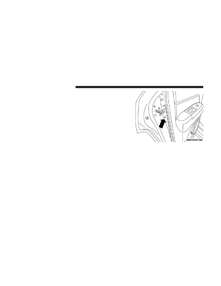
To Engage Or Disengage The Child-Protection Door
Lock System

1. Open the rear door.

2. Insert the tip of the ignition key into the lock and rotate

to the LOCK or UNLOCK position.

3. Repeat steps 1 and 2 for the opposite rear door.

Child-Protection Door Lock Location

32

GETTING TO KNOW YOUR VEHICLE

WARNING!

Avoid trapping anyone in a vehicle in a collision.
Remember that the rear doors can only be opened from
the outside when the Child-Protection locks are en-
gaged.

NOTE:

For emergency exit with the system engaged,

move the lock knob up (unlocked position), roll down the
window, and open the door with the outside door handle.

SEATS

Seats are a part of the Occupant Restraint System of the
vehicle.

WARNING!

• It is dangerous to ride in a cargo area, inside or

outside of a vehicle. In a collision, people riding in
these areas are more likely to be seriously injured or
killed.

• Do not allow people to ride in any area of your

vehicle that is not equipped with seats and seat belts.
In a collision, people riding in these areas are more
likely to be seriously injured or killed.

• Be sure everyone in your vehicle is in a seat and

using a seat belt properly.

Manual Front Seat Adjustment

On models equipped with manual seats, the adjusting bar
is located at the front of the seats, near the floor. While
sitting in the seat, lift up on the bar and move the seat
forward or rearward. Release the bar once you have

Child-Protection Door Lock Function

3

GETTING TO KNOW YOUR VEHICLE

33

reached the desired position. Then, using body pressure,
move forward and rearward on the seat to be sure that the
seat adjusters have latched.

WARNING!

• Adjusting a seat while driving may be dangerous.

Moving a seat while driving could result in loss of
control which could cause a collision and serious
injury or death.

(Continued)

WARNING! (Continued)

• Seats should be adjusted before fastening the seat

belts and while the vehicle is parked. Serious injury
or death could result from a poorly adjusted seat belt.

Manual Seat Height Adjustment — If Equipped

The driver’s seat height can be raised or lowered by using
a lever, located on the outboard side of the seat. Pull
upward on the lever to raise the seat height or push
downward on the lever to lower the seat height.

Manual Seat Adjusting Bar

Seat Height Adjustment Lever

34

GETTING TO KNOW YOUR VEHICLE

Manual Lumbar — If Equipped

The lumbar adjustment handle is located on the inboard or
outboard side of the seatback. Rotate the lever downward
to increase the lumbar support or rotate the lever upward
to decrease the lumbar support.

Driver’s Seatback Recline

To adjust the seatback, lift the lever located on the outboard
side of the seat, lean back to the desired angle and release
the lever. To return the seatback, lift the lever, lean forward
and release the lever.

WARNING!

Do not ride with the seatback reclined so that the
shoulder belt is no longer resting against your chest. In
a collision you could slide under the seat belt, which
could result in serious injury or death.

Power Seats — If Equipped

Some models may be equipped with a power driver’s seat.
The power seat switch is located on the outboard side of
the seat near the floor. Use the switch to move the seat up,
down, forward, rearward, or to tilt the seat.

Outboard Lumbar Adjustment Lever

Recline Lever

3

GETTING TO KNOW YOUR VEHICLE

35

WARNING!

• Adjusting a seat while driving may be dangerous.

Moving a seat while driving could result in loss of
control which could cause a collision and serious
injury or death.

• Seats should be adjusted before fastening the seat

belts and while the vehicle is parked. Serious injury
or death could result from a poorly adjusted seat belt.

CAUTION!

Do not place any article under a power seat or impede
its ability to move as it may cause damage to the seat
controls. Seat travel may become limited if movement
is stopped by an obstruction in the seat’s path.

Adjusting The Seat Forward Or Rearward

The seat can be adjusted both forward and rearward. Push
the seat switch forward or rearward. The seat will move in
the direction of the switch. Release the switch when the
desired position has been reached.

Adjusting The Seat Up Or Down

The height of the seats can be adjusted up or down. Pull
upward or push downward on the seat switch. The seat
will move in the direction of the switch. Release the switch
when the desired position is reached.

Tilting The Seat Up Or Down

The angle of the seat cushion can be adjusted in four
directions. Pull upward or push downward on the front or
rear of the seat switch, the front or rear of the seat cushion
will move in the direction of the switch. Release the switch
when the desired position is reached.

Power Seat Switch

36

GETTING TO KNOW YOUR VEHICLE

Heated Seats — If Equipped

On some models, the front driver and passenger seats may
be equipped with heaters in both the seat cushions and
seatbacks. The controls for the front heated seats are
located on the center instrument panel area.

You can choose from HI, LO or OFF heat settings. Amber
indicator lights in each switch indicate the level of heat in
use. Two indicator lights will illuminate for HI, one for LO
and none for OFF.

Push the switch once to select HI-level heating.
Push the switch a second time to select LO-level
heating. Push the switch a third time to shut the
heating elements OFF.

When the HI-level setting is selected, the heater will
provide a boosted heat level during the initial stages of
operation. Then, the heat output will drop to the normal
HI-level. If the HI-level setting is selected, the system will
automatically switch to LO-level after approximately 30
minutes of continuous operation. At that time, the display
will change from HI to LO, indicating the change. When
the LO-level heating is selected, the system automatically
turns the heater and the indicator light OFF after approxi-
mately 30 minutes of continuous operation.

NOTE:

Once a heat setting is selected, heat will be felt

within two to five minutes.

WARNING!

• Persons who are unable to feel pain to the skin

because of advanced age, chronic illness, diabetes,
spinal cord injury, medication, alcohol use, exhaus-
tion or other physical condition must exercise care
when using the seat heater. It may cause burns even
at low temperatures, especially if used for long
periods of time.

• Do not place anything on the seat or seatback that

insulates against heat, such as a blanket or cushion.
This may cause the seat heater to overheat. Sitting in
a seat that has been overheated could cause serious
burns due to the increased surface temperature of the
seat.

3

GETTING TO KNOW YOUR VEHICLE

37

Folding Rear Seat

To provide additional storage area, each rear seatback can
be folded forward. Pull the strap forward to fold the rear
seatback flat.

NOTE:

You may experience deformation in the seat cush-

ion from the seat belt buckles if the seats are left folded for
an extended period of time. This is normal and by simply
opening the seats to the open position, over time the seat
cushion will return to its normal shape.

To raise the seatback, pull the strap forward and lift the
seatback into its upright position.

Rear Seat Release Straps

Folded Rear Seat

38

GETTING TO KNOW YOUR VEHICLE

WARNING!

Be certain that the seatback is securely locked into
position. If the seatback is not securely locked into
position the seat will not provide the proper stability
for child seats and/or passengers. An improperly
latched seat could cause serious injury.

Reclining Rear Seat — If Equipped

For additional comfort, pull the strap forward just enough
to release the seatback latch. Then push the seatback to a
reclined position, approximately 35 degrees maximum,
and release the strap.

WARNING!

Do not ride with the seatback reclined so that the
shoulder belt is no longer resting against your chest. In
a collision you could slide under the seat belt and be
seriously or even fatally injured. Use the recliner only
when the vehicle is parked.

HEAD RESTRAINTS

Head restraints are designed to reduce the risk of injury by
restricting head movement in the event of a rear impact.
Head restraints should be adjusted so that the top of the
head restraint is located above the top of your ear.

WARNING!

• All occupants, including the driver, should not oper-

ate a vehicle or sit in a vehicle’s seat until the head
restraints are placed in their proper positions in
order to minimize the risk of neck injury in the event
of a crash.

• Head restraints should never be adjusted while the

vehicle is in motion. Driving a vehicle with the head
restraints improperly adjusted or removed could
cause serious injury or death in the event of a
collision.

3

GETTING TO KNOW YOUR VEHICLE

39

Supplemental Active Head Restraints — Front
Seats

Active Head Restraints (AHRs) are passive, deployable
components, and vehicles with this equipment cannot be
readily identified by any markings, only through visual
inspection of the head restraint. The head restraint will be
split in two halves, with the front half being soft foam and
trim, the back half being decorative plastic.

When AHRs deploy during a rear impact, the front half of
the head restraint extends forward to minimize the gap
between the back of the occupant’s head and the AHR. This
system is designed to help prevent or reduce the extent of
injuries to the driver and front passenger in certain types of
rear impacts. Refer to “Occupant Restraints” in “Safety” for
further information.

To raise the head restraint, pull upward on the head
restraint. To lower the head restraint, push the adjustment
button located at the base of the head restraint and push
downward on the head restraint.

Adjustment Button

40

GETTING TO KNOW YOUR VEHICLE

For comfort, the Active Head Restraints can be tilted
forward and backward. To tilt the head restraint closer to
the back of your head, pull forward on the bottom of the
head restraint. Push rearward on the bottom of the head
restraint to move the head restraint away from your head.

NOTE:

• The head restraints should only be removed by qualified

technicians, for service purposes only. If either of the
head restraints require removal, see your authorized
dealer.

• In the event of deployment of an Active Head Restraint,

refer to “Occupant Restraints” in “Safety” for further
information.

Active Head Restraint (Normal Position)

Active Head Restraint (Tilted Position)

3

GETTING TO KNOW YOUR VEHICLE

41

WARNING!

• All occupants, including the driver, should not oper-

ate a vehicle or sit in a vehicle’s seat until the head
restraints are placed in their proper positions in
order to minimize the risk of neck injury in the event
of a collision.

• Do not place items over the top of the Active Head

Restraint, such as coats, seat covers or portable DVD
players. These items may interfere with the opera-
tion of the Active Head Restraint in the event of a
collision and could result in serious injury or death.

• Active Head Restraints may be deployed if they are

struck by an object such as a hand, foot or loose
cargo. To avoid accidental deployment of the Active
Head Restraint ensure that all cargo is secured, as
loose cargo could contact the Active Head Restraint
during sudden stops. Failure to follow this warning
could cause personal injury if the Active Head Re-
straint is deployed.

Rear Head Restraints

The head restraints in the rear are non adjustable. Refer to
“Occupant Restraints” in “Safety” for information on
Tether routing.

STEERING WHEEL

Tilt Steering Column

This feature allows you to tilt the steering column upward
or downward. The tilt steering column lever is located on
the left side of the steering column, below the turn signal
lever.

Push down on the lever to unlock the steering column.
With one hand firmly on the steering wheel, move the
steering column up or down, as desired. Push the lever up
to lock the steering column firmly in place.

Tilt Steering Column Lever

42

GETTING TO KNOW YOUR VEHICLE

WARNING!

Do not adjust the steering column while driving.
Adjusting the steering column while driving or driv-
ing with the steering column unlocked, could cause the
driver to lose control of the vehicle. Failure to follow
this warning may result in serious injury or death.

MIRRORS

Inside Day/Night Mirror

A two-point pivot system allows for horizontal and vertical
mirror adjustment. Adjust the mirror to center on the view
through the rear window.

Headlight glare can be reduced by moving the small
control under the mirror to the night position (toward the
rear of vehicle). The mirror should be adjusted while set in
the day position (toward the windshield).

Inside Day/Night Mirror

3

GETTING TO KNOW YOUR VEHICLE

43

Automatic Dimming Mirror — If Equipped

This mirror automatically adjusts for headlight glare from
vehicles behind you. You can turn the feature on or off by
pushing the button at the base of the mirror. The On/Off
symbol on the button will illuminate when the auto-
dimming feature is enabled.

NOTE:

This feature is disabled when the vehicle is mov-

ing in reverse.

CAUTION!

To avoid damage to the mirror during cleaning, never
spray any cleaning solution directly onto the mirror.
Apply the solution onto a clean cloth and wipe the
mirror clean.

Outside Mirror — Driver Side

Adjust the flat outside mirror so you can just see the side of
your vehicle in the part of the mirror closest to the vehicle
with your head close to the door glass.

Outside Mirror — Passenger Side

Adjust the convex outside mirror so you can just see the
side of your vehicle in the part of the mirror closest to the
vehicle with your head close to the center of the vehicle.

WARNING!

Vehicles and other objects seen in the passenger side
convex mirror will look smaller and farther away than
they really are. Relying too much on your passenger
side convex mirror could cause you to collide with
another vehicle or other object. Use your inside mirror

(Continued)

Automatic Dimming Mirror

44

GETTING TO KNOW YOUR VEHICLE

WARNING! (Continued)

when judging the size or distance of a vehicle seen in
the passenger side convex mirror. Some vehicles will
not have a convex passenger side mirror.

Folding Outside Mirrors

The outside mirrors are hinged and may be moved, manu-
ally, either forward or rearward to resist damage. The
hinges have three detent positions; full forward, full rear-
ward and normal.

Power Mirrors

The power mirror control is located on the driver’s door
trim panel.

To adjust a mirror, turn the control wand toward the left or
right mirror positions indicated. Tilt the control wand in
the direction you want the mirror to move.

When you are finished adjusting the mirror, turn the
control to the center position to prevent accidentally mov-
ing a mirror.

Power Mirror Control

3

GETTING TO KNOW YOUR VEHICLE

45

Heated Mirrors — If Equipped

These mirrors are heated to melt frost or ice. This
feature is activated whenever you turn on the rear

window defroster. Refer to “Automatic Temperature Con-
trol (ATC) — If Equipped” in “Getting To Know Your
Vehicle” for further information.

Vanity Mirrors — If Equipped

To use the vanity mirror, rotate the sun visor down and
swing the mirror cover upward.

Sun Visor “Slide-On-Rod” Feature — If Equipped

The sun visors may be extended out to provide more
coverage of the side glass.

EXTERIOR LIGHTS

Headlights And Parking Lights

Turn the end of the multifunction lever to the first detent to
turn on the parking lights. Turn the end of the lever to the
second detent to turn on the headlights.

Vanity Mirror

Headlight Control

46

GETTING TO KNOW YOUR VEHICLE

Daytime Running Lights — If Equipped

The high beam lights will come on as Daytime Running
Lights (lower intensity), whenever the ignition is ON, the
engine is running, the headlight switch is off, the parking
brake is off, the turn signal is off, and the gear selector is in
any position except PARK.

High/Low Beam Switch

Push the multifunction lever away from you to switch the
headlights to high beam. Pull the multifunction lever
toward you to switch the headlights back to low beam.

Flash-To-Pass

You can signal another vehicle with your headlights by
lightly pulling the multifunction lever toward you. This
will turn on the high beam headlights until the lever is
released.

NOTE:

If the multifunction lever is held in the flash-to-

pass position for more than 20 seconds, the high beams will
shut off. If this occurs, wait 30 seconds for the next
flash-to-pass operation.

Automatic Headlights — If Equipped

Turning the end of the multifunction lever to the third
detent (AUTO), will activate the automatic headlight sys-
tem.

With the engine running and the multifunction lever in the
AUTO position, the headlights will turn on and turn off
based on the surrounding light levels.

Headlight Switch

3

GETTING TO KNOW YOUR VEHICLE

47


Content   ..  1  2  3  4   ..