Jeep Liberty (2012 year). Instruction - part 10


  Index      Jeep     Jeep Liberty - instruction 2012 year in english


Search            


Content   ..  8  9  10  11   ..


Jeep Liberty (2012 year). Instruction - part 10


Manual Lumbar Support — If Equipped

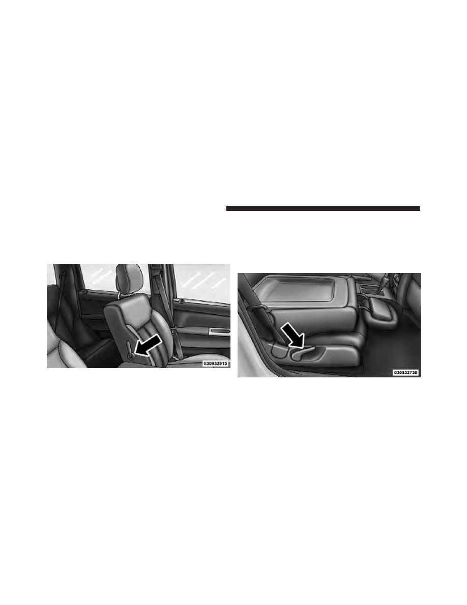
For models equipped with manual lumbar the support
lever is located on the inboard side of the seat. Turn the
lever downward to increase and upward to decrease the
desired amount of lumbar support.

Fold-Flat Front Passenger Seat — If Equipped

This feature allows the front passenger seatback to fold
flat for extended cargo space. Some fold flat seats also
have a hardback surface that you can use as a work
surface when the seat is folded flat. Pull up on the lever
to fold down the seatback.

Lumbar Support Lever

Fold-Flat Passenger Seat

144

UNDERSTANDING THE FEATURES OF YOUR VEHICLE

Head Restraints

Head restraints are designed to reduce the risk of injury
by restricting head movement in the event of a rear
impact. Head restraints should be adjusted so that the top
of the head restraint is located above the top of your ear.

WARNING!

The head restraints for all occupants must be prop-
erly adjusted prior to operating the vehicle or occu-
pying a seat. Head restraints should never be ad-
justed while the vehicle is in motion. Driving a
vehicle with the head restraints improperly adjusted
or removed could cause serious injury or death in the
event of a collision.

Active Head Restraints — Front Seats
Active Head Restraints are passive, deployable compo-
nents, and vehicles with this equipment cannot be readily
identified by any markings, only through visual inspec-
tion of the head restraint. The head restraint will be split
in two halves, with the front half being soft foam and
trim, the back half being decorative plastic.

When AHRs deploy during a rear impact, the front half
of the head restraint extends forward to minimize the gap
between the back of the occupant’s head and the AHR.
This system is designed to help prevent or reduce the
extent of injuries to the driver and front passenger in
certain types of rear impacts. Refer to “Occupant Re-
straints” in “Things To Know Before Starting Your Ve-
hicle” for further information.

3

UNDERSTANDING THE FEATURES OF YOUR VEHICLE

145

To raise the head restraint, pull upward on the head
restraint. To lower the head restraint, press the adjust-
ment button, located at the base of the head restraint, and
push downward on the head restraint.

For comfort the Active Head Restraints can be tilted
forward and backward. To tilt the head restraint closer to
the back of your head, pull forward on the bottom of the
head restraint. Push rearward on the bottom of the head
restraint to move the head restraint away from your
head.

Adjustment Button

Active Head Restraint (Normal Position)

146

UNDERSTANDING THE FEATURES OF YOUR VEHICLE

NOTE:

• The head restraints should only be removed by quali-

fied technicians, for service purposes only. If either of
the head restraints require removal, see your autho-
rized dealer.

• In the event of deployment of an Active Head Re-

straint, refer to “Occupant Restraints/Resetting Active
Head Restraints (AHR)” in “Things To Know Before
Starting Your Vehicle” for further information.

WARNING!

• Do not place items over the top of the Active Head

Restraint, such as coats, seat covers or portable
DVD players. These items may interfere with the
operation of the Active Head Restraint in the event
of a collision and could result in serious injury or
death.

(Continued)

Active Head Restraint (Tilted)

3

UNDERSTANDING THE FEATURES OF YOUR VEHICLE

147

WARNING! (Continued)

• Active Head Restraints may be deployed if they

are struck by an object such as a hand, foot or loose
cargo. To avoid accidental deployment of the Ac-
tive Head Restraint ensure that all cargo is se-
cured, as loose cargo could contact the Active Head
Restraint during sudden stops. Failure to follow
this warning could cause personal injury if the
Active Head Restraint is deployed.

Rear Head Restraints
The two outboard seat are equipped with adjustable head
restraints. To raise the head restraint, pull upward on the
head restraint. To lower the head restraint, press the
adjustment button, located on the base of the head
restraint, and push downward on the head restraint.

NOTE:

• The head restraints should only be removed by quali-

fied technicians, for service purposes only. If either of
the head restraints require removal, see your autho-
rized dealer.

Adjustment Button

148

UNDERSTANDING THE FEATURES OF YOUR VEHICLE

• Refer to “Occupant Restraints” in “Things To Know

Before Starting Your Vehicle” for information on tether
routing.

WARNING!

Driving a vehicle with the head restraints removed or
improperly adjusted could cause serious injury or
death in the event of a collision. The head restraints
should be checked prior to operating the vehicle and
never adjusted while the vehicle is in motion.

60/40 Split Folding Rear Seat With Fold-Flat
Feature

To provide additional storage area, each rear seat can be
folded flat. This allows for extended cargo space and still
maintains some rear seating room.

NOTE:

Prior to folding the rear seat, it may be necessary

to position the front seat to its mid-track position. Also,

be sure that the front seats are fully upright and posi-
tioned forward. This will allow the rear seat to fold down
easily.

WARNING!

• It is extremely dangerous to ride in a cargo area,

inside or outside of a vehicle. In a collision, people
riding in these areas are more likely to be seri-
ously injured or killed.

• Do not allow people to ride in any area of your

vehicle that is not equipped with seats and seat
belts.

• Be sure everyone in your vehicle is in a seat and

using a seat belt properly.

To Lower The Rear Seat

1. Locate the release strap on the lower outboard side of
each rear seatback.

3

UNDERSTANDING THE FEATURES OF YOUR VEHICLE

149

2. Pull the release strap (toward the front of the vehicle).

3. Fold the rear seat completely forward.

4. If desired, push down on the seatback to lock it in the
folded position.

To Raise The Rear Seat

NOTE:

If interference from the cargo area prevents the

seatback from fully locking, you will have difficulty
returning the seat to its proper position.

1. If locked in the folded position, pull the release strap
(toward the front of the vehicle).

2. Raise the seatback and lock it into place.

WARNING!

Be certain that the seatback is securely locked into
position. If the seatback is not securely locked into
position the seat will not provide the proper stability
for child seats and/or passengers. An improperly
latched seat could cause serious injury.

Rear Seat Release Strap

150

UNDERSTANDING THE FEATURES OF YOUR VEHICLE

Recliner Adjustment
The rear seatback also reclines for additional passenger
comfort. Pull the release strap while sitting in the rear
seat to recline the seatback.

WARNING!

Do not ride with the seatback reclined so that the
shoulder belt is no longer resting against your chest.
In a collision you could slide under the seat belt,
which could result in serious injury or death.

DRIVER MEMORY SEAT — IF EQUIPPED

This feature allows the driver to store up to two different
memory profiles, for easy recall through a memory
switch. Each memory profile contains desired position
settings for the driver seat and side mirrors and a set of
desired radio station presets.

The memory switch is located on the instrument panel to
the left of the steering column. The switch contains a S
(SET) button to activate the memory save function. It also
contains a rocker switch labeled with the number (1) and
the number (2). The rocker switch allows the driver to

Rear Seatback Release Strap

3

UNDERSTANDING THE FEATURES OF YOUR VEHICLE

151

recall either of the two pre-programmed memory profiles
by pressing the appropriate side of the switch.

Programming The Memory Feature

To create a new memory profile, perform the following:

NOTE:

Saving a new memory profile will erase an

existing profile from memory.

1. Turn the ignition ON.

2. Adjust all memory profile settings to desired prefer-
ences (i.e., seat, side mirror and radio station presets).

3. Press and release the SET button on the memory
switch, then press the side of the rocker switch labeled (1)
within five seconds. The Electronic Vehicle Information
Center (EVIC), if equipped, will display which memory
position is being set.

If desired, a second memory profile can be stored into
memory as follows:

1. Turn the ignition ON.

2. Adjust all memory profile settings to desired prefer-
ences (i.e., seat, side mirror and radio station presets).

Driver Memory Switch

152

UNDERSTANDING THE FEATURES OF YOUR VEHICLE

3. Press and release the SET button on the memory
switch, then press the side of the rocker switch labeled (2)
within five seconds. The EVIC, if equipped, will display
which memory position is being set.

NOTE:

• For vehicles equipped with an automatic transmission,

memory profiles can be set without the vehicle in
PARK, but the vehicle must be in PARK to recall a
memory profile.

• For vehicles equipped with a manual transmission, the

vehicle speed must be at 0 mph (0 km/h) to recall a
memory profile.

• The Recall Memory with Remote Key Unlock feature

can be turned on and off through the EVIC, if
equipped. Refer to “Electronic Vehicle Information
Center (EVIC)/Customer-Programmable Features” in
“Understanding Your Instrument Panel” for further
information.

Linking And Unlinking The Remote Keyless Entry
Transmitter To Memory

Your Remote Keyless Entry (RKE) transmitters can be
programmed to recall one of two pre-programmed
memory profiles with a press of the UNLOCK button on
the RKE transmitter.

To program your RKE transmitters, perform the follow-
ing:

1. Remove the key from the ignition.

2. Select the desired memory profile 1 or 2.

3. Press and release the SET button on the memory
switch, then within five seconds press and release the
side of the rocker switch labeled 1 or 2 accordingly.

⬙Memory Profile Set” (1 or 2) will display in the EVIC, if
equipped.

4. Press and release the LOCK button on the RKE
transmitter within 10 seconds.

3

UNDERSTANDING THE FEATURES OF YOUR VEHICLE

153

NOTE:

Your RKE transmitters can be unlinked to the

memory setting by pressing the SET button followed by
the UNLOCK button on the RKE transmitter in Step 4
above.

Memory Position Recall

NOTE:

• For vehicles equipped with an automatic transmission,

the vehicle must be in PARK to recall memory posi-
tions. If a recall is attempted when the vehicle is not in
PARK, a message will display in the EVIC, if
equipped.

• For vehicles equipped with a manual transmission, the

vehicle speed must be at 0 mph (0 km/h) to recall
memory positions. If a recall is attempted with the
vehicle speed above 0 mph (0 km/h), a message will
display in the EVIC, if equipped.

To recall the memory settings for driver one, press
MEMORY button number 1 or the UNLOCK button on
the RKE transmitter linked to memory position 1.

To recall the memory setting for driver two, press
MEMORY button number 2 or the UNLOCK button on
the RKE transmitter linked to memory position 2.

A recall can be cancelled by pressing any of the
MEMORY buttons (S, 1, or 2) during a recall. When a
recall is cancelled, the driver seat will stop moving. A
delay of one second will occur before another recall can
be selected.

154

UNDERSTANDING THE FEATURES OF YOUR VEHICLE

Easy Entry/Exit Seat
(Available With Memory Seat Only)

This feature provides automatic driver seat positioning to
enhance driver mobility when entering and exiting the
vehicle.

The distance the driver seat moves depends on where
you have the driver seat positioned when you remove the
key from the ignition switch.

• When you remove the key from the ignition switch,

the driver seat will move about 2.4 in (60 mm)
rearward if the driver’s seat position is greater than or
equal to 2.7 in (68 mm) forward of the rear stop. The
seat will return to its previously set position when you
insert the key into the ignition switch and turn it out of
the LOCK position.

• When you remove the key from the ignition switch,

the driver seat will move to a position 0.3 in (8 mm)
forward of the rear stop if the driver’s seat position is

between 0.9 in and 2.7 in (23 mm and 68 mm) forward
of the rear stop. The seat will return to its previously
set position when you insert the key into the ignition
switch and turn it out of the LOCK position.

• The Easy Entry/Easy Exit feature is disabled when the

driver’s seat position is less than 0.9 in (23 mm)
forward of the rear stop. At this position, there is no
benefit to the driver by moving the seat for Easy Exit
or Easy Entry.

Each stored memory setting will have an associated Easy
Entry and Easy Exit position.

NOTE:

The Easy Entry/Easy Exit feature can be turned

on or off through the programmable features in the EVIC.
Refer to “Electronic Vehicle Information Center (EVIC)/
Customer-Programmable Features” in “Understanding
Your Instrument Panel” for further information.

3

UNDERSTANDING THE FEATURES OF YOUR VEHICLE

155

TO OPEN AND CLOSE THE HOOD

Two latches must be released to open the hood.

1. Pull the hood release lever located under the left side
of the instrument panel.

2. Outside of the vehicle, locate the safety latch lever
between the grille and hood opening (left of center when
facing hood). Push the safety latch lever to the right and
then raise the hood.

Hood Release

Underhood Safety Latch

156

UNDERSTANDING THE FEATURES OF YOUR VEHICLE

Use the hood prop rod to secure the hood in the open
position. Place the upper end of the prop rod in the hole
on the underside of the hood.

CAUTION!

To prevent possible damage:
• Before closing hood, make sure the hood prop rod

is fully seated into its storage retaining clips.

• Lower the hood to approximately 6 in (15.2 cm)

above the closed position and drop the hood to
latch it.

• Never drive your vehicle unless the hood is fully

closed, with both latches engaged.

WARNING!

Be sure the hood is fully latched before driving your
vehicle. If the hood is not fully latched, it could open
when the vehicle is in motion and block your vision.
Failure to follow this warning could result in serious
injury or death.

3

UNDERSTANDING THE FEATURES OF YOUR VEHICLE

157

LIGHTS

Multifunction Lever

The multifunction lever on the left side of the steering
column controls the operation of the headlights, parking
lights, turn signal lights, instrument panel lights, instru-
ment panel light dimming, interior lights and fog lights
(if equipped).

Headlights And Parking Lights

Turn the end of the multifunction lever to the first detent
for parking light operation. Turn the end of the lever to
the second detent for headlight operation.

Multifunction Lever

Headlight Switch

158

UNDERSTANDING THE FEATURES OF YOUR VEHICLE

Automatic Headlights — If Equipped

This system automatically turns the headlights on or off
according to ambient light levels. To turn the system on,
turn the end of the multifunction lever to the AUTO
position (third detent). When the system is on, the
Headlight Time Delay feature is also on. This means the
headlights will stay on for up to 90 seconds after you turn
the ignition switch to the LOCK position. To turn the
Automatic System off, turn the end of the multifunction
lever out of the AUTO position.

NOTE:

The engine must be running before the head-

lights will turn on in the Automatic mode.

Headlight Switch

3

UNDERSTANDING THE FEATURES OF YOUR VEHICLE

159


Content   ..  8  9  10  11   ..