Jeep XJ. Manual - part 105
(2) Install and tighten the seven screws that
secure the inner glove box door to the outer glove box
door. Tighten the screws to 2.2 N·m (20 in. lbs.).
(3) Install the glove box onto the instrument panel.
Refer to Glove Box - Installation in the Removal
and Installation section of this group for the proce-
dures.
(4) Reconnect the battery negative cable.
GLOVE BOX OUTER DOOR
(1) Position the outer glove box door onto the inner
glove box door unit.
(2) Install and tighten the seven screws that
secure the inner glove box door to the outer glove box
door. Tighten the screws to 2.2 N·m (20 in. lbs.).
(3) Install the glove box onto the instrument panel.
Refer to Glove Box - Installation in the Removal
and Installation section of this group for the proce-
dures.
(4) Reconnect the battery negative cable.
GLOVE BOX LOCK CYLINDER
(1) To install the lock cylinder, insert the key into
the cylinder and align the lock cylinder tumblers
with the ramp in the glove box latch lock cylinder
bore. The ramp is located at about the 7 o’clock posi-
tion.
(2) Push the glove box lock cylinder firmly into the
lock cylinder bore while rotating the key and cylinder
counterclockwise to the 6 o’clock position, where the
lock cylinder retaining tumbler will snap back into
place.
GLOVE BOX LATCH STRIKER
WARNING: ON VEHICLES EQUIPPED WITH AIR-
BAGS,
REFER
TO
GROUP
8M
-
PASSIVE
RESTRAINT SYSTEMS BEFORE ATTEMPTING ANY
STEERING
WHEEL,
STEERING
COLUMN,
OR
INSTRUMENT PANEL COMPONENT DIAGNOSIS OR
SERVICE. FAILURE TO TAKE THE PROPER PRE-
CAUTIONS COULD RESULT IN ACCIDENTAL AIR-
BAG DEPLOYMENT AND POSSIBLE PERSONAL
INJURY.
REMOVAL
(1) Disconnect and isolate the battery negative
cable.
(2) Open the glove box.
(3) Remove the passenger side airbag module from
the instrument panel. Refer to Passenger Side Air-
bag Module in the Removal and Installation section
of Group 8M - Passive Restraint Systems for the pro-
cedures.
(4) Remove the two screws that secure the latch
striker to the instrument panel glove box opening
upper reinforcement (Fig. 20).
(5) Remove the latch striker from the instrument
panel glove box opening upper reinforcement.
INSTALLATION
(1) Position the latch striker onto the instrument
panel glove box opening upper reinforcement.
(2) Install and tighten the two screws that secure
the latch striker to the instrument panel glove box
opening upper reinforcement. Tighten the screws to
2.2 N·m (20 in. lbs.).
(3) Install the passenger side airbag module onto
the instrument panel. Refer to Passenger Side Air-
bag Module in the Removal and Installation section
of Group 8M - Passive Restraint Systems for the pro-
cedures.
(4) Close the glove box.
(5) Reconnect the battery negative cable.
Fig. 19 Glove Box Lock Cylinder Remove/Install
1 – LOCK CYLINDER
2 – LATCH HANDLE
3 – RELEASE HOLE
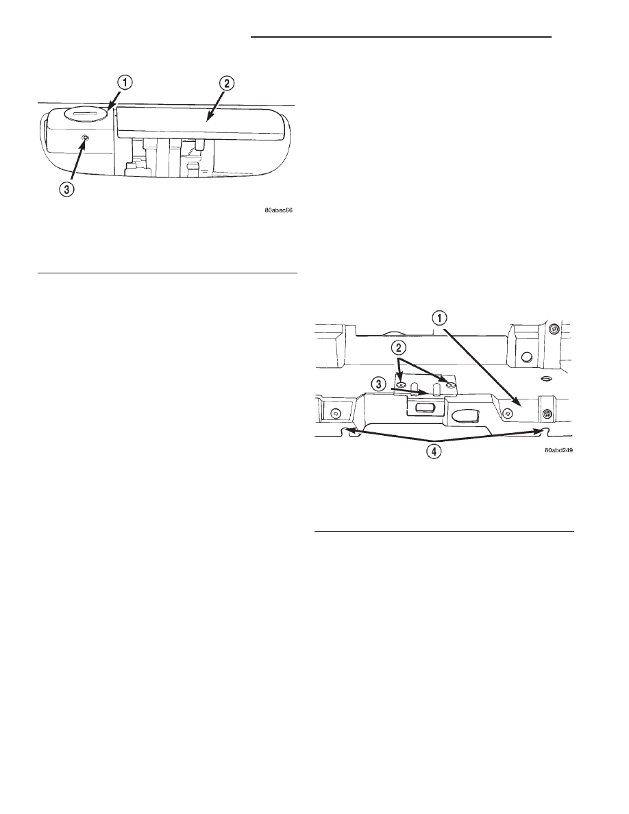
Fig. 20 Glove Box Latch Striker Remove/Install
1 – GLOVE BOX OPENING UPPER REINFORCEMENT
2 – SCREWS
3 – LATCH STRIKER
4 – STOP BUMPER SLOTS
8E - 24
INSTRUMENT PANEL SYSTEMS
XJ
REMOVAL AND INSTALLATION (Continued)