Jeep Wrangler TJ. Manual - part 291
DIAGNOSIS AND TESTING
REAR WINDOW DEFOGGER SWITCH
WARNING: On vehicles equipped with airbags, dis-
able the airbag system before attempting any steer-
ing wheel, steering column, or instrument panel
component diagnosis or service. Disconnect and
isolate the battery negative (ground) cable, then
wait two minutes for the airbag system capacitor to
discharge before performing further diagnosis or
service. Failure to take the proper precautions
could result in accidental airbag deployment and
possible personal injury or death.
NOTE: For circuit descriptions and diagrams, refer
to Rear Window Defogger in Group 8W - Wiring Dia-
grams.
(1) Disconnect and isolate the negative battery
cable. Remove the accessory switch bezel from the
instrument panel and disconnect the wire harness
connector from the defogger switch.
(2) Check for continuity between the ground cir-
cuit cavity of the defogger switch wire harness con-
nector
and
a
good
ground.
There
should
be
continuity. If OK, go to Step 3. If not OK, repair the
open circuit as required.
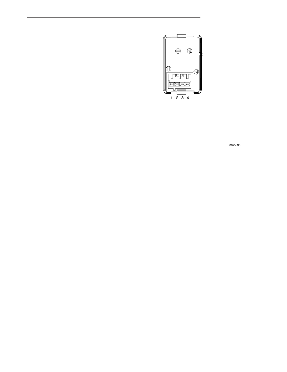
(3) Check for continuity between the ground cir-
cuit terminal and the rear window defogger switch
sense circuit terminal on the back of the defogger
switch housing (Fig. 7). There should be momentary
continuity as the defogger switch is pressed, and
then no continuity. If OK, test the instrument cluster
(Refer to 8 - ELECTRICAL/INSTRUMENT CLUS-
TER - DIAGNOSIS AND TESTING). If not OK,
replace the faulty rear window defogger switch (Refer
to 8 - ELECTRICAL/HEATED GLASS/REAR WIN-
DOW DEFOGGER SWITCH - REMOVAL).
REMOVAL
WARNING: On vehicles equipped with airbags, dis-
able the airbag system before attempting any steer-
ing wheel, steering column, or instrument panel
component diagnosis or service. Disconnect and
isolate the battery negative (ground) cable, then
wait two minutes for the airbag system capacitor to
discharge before performing further diagnosis or
service. Failure to take the proper precautions
could result in accidental airbag deployment and
possible personal injury or death.
(1) Disconnect and isolate the negative battery
cable.
(2) Remove the center bezel from the instrument
panel (Refer to 23 - BODY/INSTRUMENT PANEL/
CLUSTER BEZEL - REMOVAL).
(3) Remove the four screws that secure the acces-
sory switch bezel to the instrument panel (Fig. 8).
(4) Pull the accessory switch bezel out from the
instrument panel far enough to access the wire har-
ness connectors.
(5) Disconnect the wire harness connectors from
the rear of the accessory switches and the cigar light-
er/power outlet.
(6) Remove the accessory switch bezel from the
instrument panel.
(7) Using a small thin-bladed screwdriver, gently
pry the snap clips at the top and at the bottom of the
rear window defogger switch receptacle on the back
of the accessory switch bezel and pull the switch out
of the bezel.
INSTALLATION
(1) Install the rear window defogger switch into
the back of the accessory switch bezel by pushing the
switch firmly into the bezel.
(2) Connect the wire harness connectors to the
rear of the accessory switches and the cigar lighter/
power outlet.
(3) Install the accessory switch bezel to the instru-
ment panel.
Fig. 7 Rear Window Defogger Switch Continuity
SWITCH POSITION
CONTINUITY BETWEEN
OFF
LAMPS
ON
MOMENTARY 1 AND 2
ILLUMINATION LAMP
1 AND 4
INDICATOR LAMP
1 AND 3
TJ
HEATED GLASS
8G - 5
REAR WINDOW DEFOGGER SWITCH (Continued)