Content .. 1373 1374 1375 1376 ..
Jeep Liberty KJ. Manual - part 1375
HVAC - SERVICE INFORMATION
DESCRIPTION
A manual temperature control (MTC) single zone type heating-A/C system is standard equipment on this vehicle.
To maintain the performance level of the heating, ventilation and air conditioning (HVAC) system, the engine cooling
system must be properly maintained. The use of a bug screen is not recommended. Any obstructions in front of the
radiator or A/C condenser will reduce the performance of the A/C and engine cooling systems.
The engine cooling system includes the radiator, thermostat, radiator hoses and the engine coolant pump. Refer to
7 - Cooling for more information before opening or attempting any service to the engine cooling system.
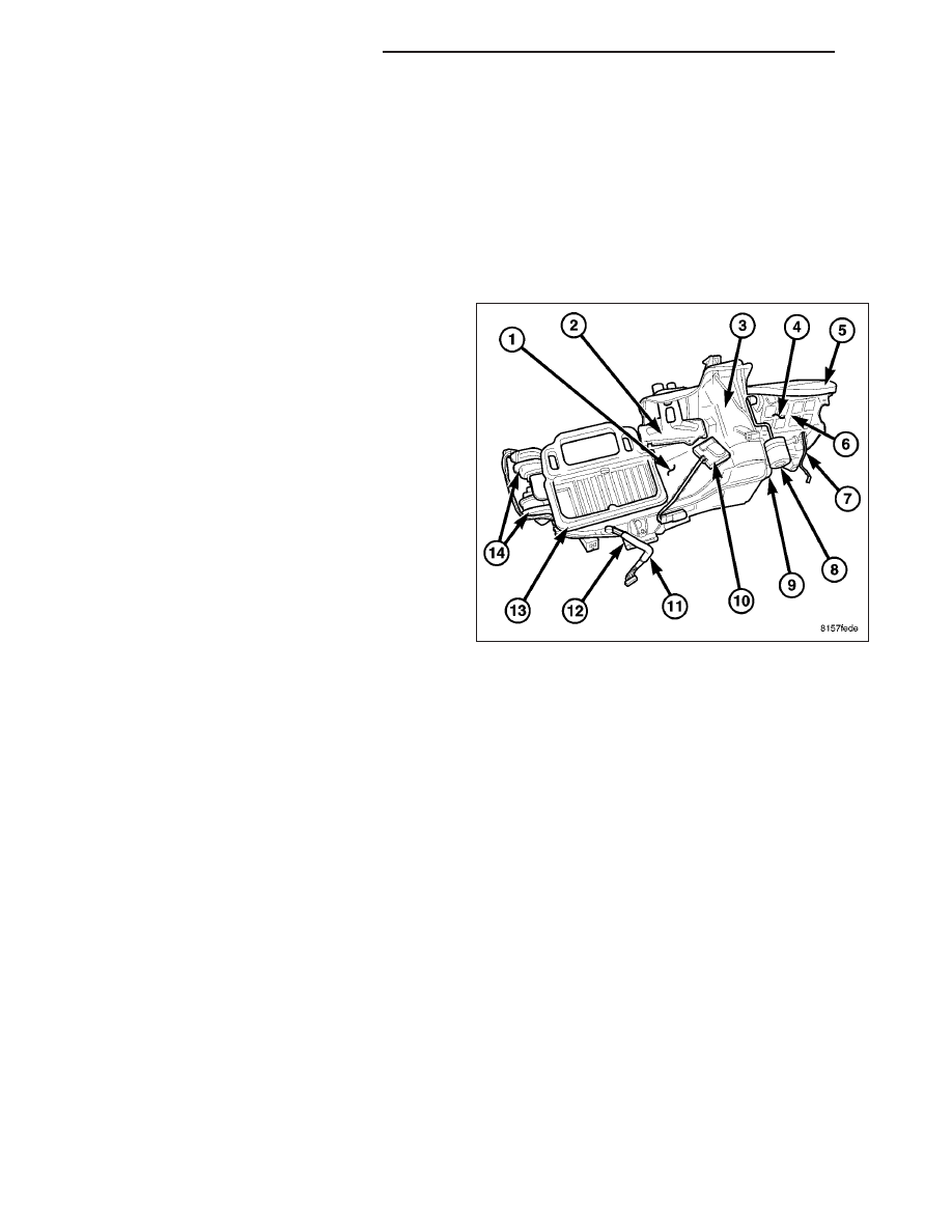
All vehicles are equipped with a common heater, ven-
tilation and air conditioning (HVAC) housing (1). The
heating-A/C system combines A/C, heating, and venti-
lating capabilities in a single HVAC housing mounted
within the passenger compartment behind the instru-
ment panel. The HVAC housing includes:
•
Heater core (2)
•
A/C evaporator (3)
•
Air inlet housing (4) and foam seal (5)
•
Recirculation-air door (6)
•
Blower motor (7)
•
Recirculation door actuator (8)
•
Blower motor resistor (9)
•
Blend-air doors and actuator (10)
•
HVAC vacuum harness (11)
•
Floor distribution duct (12)
•
Mode-air doors (13)
•
Mode door actuators (14)
Based upon the mode selected, conditioned air can exit the HVAC housing through one or a combination of the
three main housing outlets: defrost, panel or floor. The defrost and panel outlets are located on the top of the hous-
ing and the floor outlet is located on the bottom of the housing. Once the conditioned air exits the HVAC housing,
it is further directed through molded plastic ducts to the outlets within the vehicle interior. These outlets and their
locations are as follows:
•
Defroster Outlet - Dual defroster outlets are located in the center of the instrument panel top cover, near the
base of the windshield.
•
Side Window Demister Outlets - There are two side window demister outlets, one is located at each out-
board end of the instrument panel top cover, near the belt line at the A-pillars.
•
Panel Outlets - There are four panel outlets in the instrument panel, one located near each outboard end of
the instrument panel facing the rear of the vehicle and two located near the top of the instrument panel center
bezel.
•
Front Floor Outlets - There are two front floor outlets, one located above each side of the center of the floor
panel near the dash panel.
•
Rear Floor Outlets - There are four rear floor outlets, two located on each side of the floor console near the
rear of each front seat.
OPERATION
The heating-A/C system used in this vehicle is a single zone, blend-air type system. In this blend-air heating-A/C
system, a blend-air door controls the amount of conditioned air that is allowed to flow through, or around, the heater
core. The temperature control adjusts discharge air temperature by operating an electric actuator, which operates
the blend-air door. This allows an almost immediate control of the output air temperature of the system. The A/C
system is designed for the use of non-CFC, R-134a refrigerant and uses an A/C evaporator to cool and dehumidify
the incoming air prior to blending it with the heated air.
24 - 2
HEATING & AIR CONDITIONING
KJ