Jeep Grand Cherokee WK. Manual - part 659
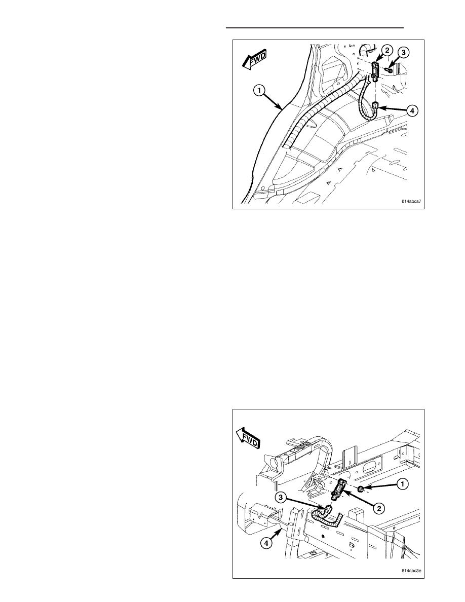
1. Disconnect and isolate the battery negative cable.
Wait two minutes for the system capacitor to dis-
charge before further service.
2. Remove the quarter trim panel from the lower
C-pillar. (Refer to 23 - BODY/INTERIOR/QUARTER
TRIM PANEL - REMOVAL).
3. Remove the two screws (3) that secure the side
impact sensor (2) to the C-pillar (1).
4. Disconnect the body wire harness connector (4)
from the sensor connector receptacle.
5. Remove the sensor from the C-pillar.
INSTALLATION
FRONT
WARNING: To avoid personal injury or death, on vehicles equipped with airbags, disable the supplemental
restraint system before attempting any steering wheel, steering column, airbag, occupant classification sys-
tem, seat belt tensioner, impact sensor, or instrument panel component diagnosis or service. Disconnect
and isolate the battery negative (ground) cable, then wait two minutes for the system capacitor to discharge
before performing further diagnosis or service. This is the only sure way to disable the supplemental
restraint system. Failure to take the proper precautions could result in accidental airbag deployment.
WARNING: To avoid personal injury or death, never strike or drop the front impact sensor, as it can damage
the impact sensor or affect its calibration. The front impact sensor enables the system to deploy the front
supplemental restraints. If an impact sensor is accidentally dropped during service, the sensor must be
scrapped and replaced with a new unit. Failure to observe this warning could result in accidental, incom-
plete, or improper front supplemental restraint deployment.
NOTE: The front and side impact sensors are interchangeable.
1. Position the right or left front impact sensor (2) into
the engine compartment.
2. Reconnect the headlamp and dash wire harness
connector (3) to the sensor connector receptacle.
3. Carefully position the sensor onto the studs on the
back of the right or left radiator support vertical
member. Be certain that the anti-rotation pin on the
back of the sensor is engaged in the center clear-
ance hole of the radiator support and the arrow on
the sensor label is pointed forward in the vehicle.
4. Install and tighten the two nuts that secure the sen-
sor to the back of the support vertical member.
Tighten the nuts to 8 N·m (70 in. lbs.).
5. Do not reconnect the battery negative cable at this
time. The supplemental restraint system verification
test procedure should be performed following ser-
vice of any supplemental restraint system compo-
8O - 458
RESTRAINTS - SERVICE INFORMATION
WK