Content .. 1539 1540 1541 1542 ..
Jeep Grand Cherokee WK. Manual - part 1541
C2113–DRIVETRAIN SENSOR SUPPLY VOLTAGE CIRCUIT OPEN (FDCM) (CONTINUED)
For a complete wiring diagram Refer to Section 8W
•
When Monitored:
With the ignition on and no system undervoltage or overvoltage condition present.
•
Set Condition:
The Final Drive Control Module detects that the 5V Supply (Reference) Voltage is correct, but the Transfer
Case Selector Switch and Mode Sensor indicate a low voltage condition.
Possible Causes
INTERMITTENT DRIVETRAIN SENSOR SUPPLY VOLTAGE CIRCUIT OPEN
(K504) DRIVETRAIN 5 VOLT SUPPLY CIRCUIT OPEN
(K594) DRIVETRAIN SENSOR RETURN CIRCUIT OPEN
FINAL DRIVE CONTROL MODULE
Diagnostic Test
1.
DTC IS ACTIVE
Ignition on.
With the scan tool, select View DTCs.
Is the status Active for this DTC?
Yes
>> Go to 2
No
>> Go to 5
2.
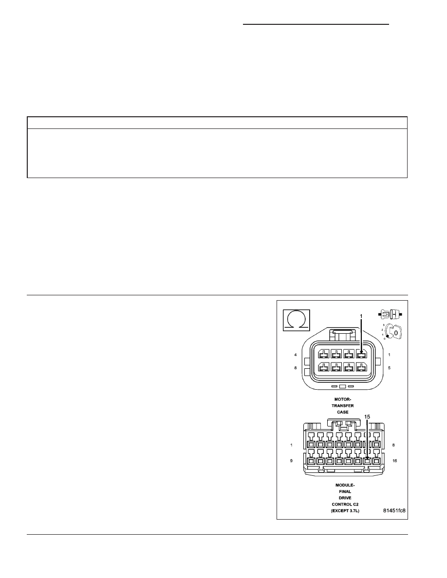
(K504) DRIVETRAIN 5 VOLT SUPPLY CIRCUIT OPEN
Turn the ignition off.
Disconnect the Transfer Case Motor harness connector.
Disconnect the Final Drive Control Module C2 harness connector.
Measure the resistance of the (K504) Drivetrain 5 Volt Supply circuit.
Is the resistance above 5.0 ohms?
Yes
>> Repair the (K504) Drivetrain 5 Volt Supply circuit for an
open.
Perform the TRANSFER CASE VERIFICATION TEST-
VER 1.
No
>> Go to 3
21 - 974
TRANSFER CASE - ELECTRICAL DIAGNOSTICS
WK