Content .. 1510 1511 1512 1513 ..
Jeep Grand Cherokee WK. Manual - part 1512
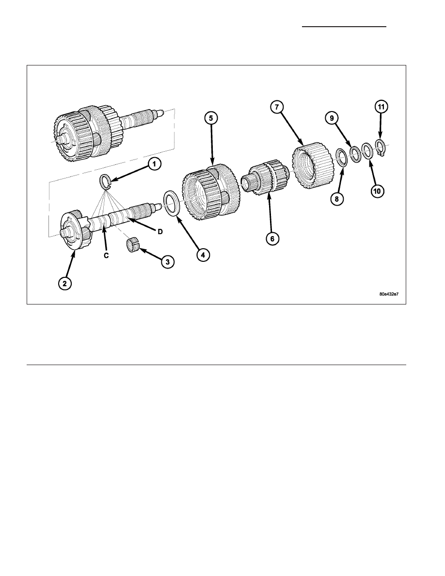
DISASSEMBLY
1. Remove upper two visible Teflon rings (1) from output shaft.
2. Remove retaining ring (11), shim (10), thrust needle bearing (9) and thrust washer (8) from output shaft.
3. Remove clutch K3 (7).
4. Remove rear tubular shaft/freewheeling clutch F2 (6) from output shaft.
5. Remove rear gear set (5) with integrated tubular shaft of center gear set from output shaft.
6. Remove thrust washer (4).
Output Shaft with Center and Rear Planetary Geartrain
1 - TEFLON RINGS
7 - DRIVING CLUTCH K3
2 - OUTPUT SHAFT WITH CENTER PLANETARY CARRIER
8 - THRUST WASHER
3 - NEEDLE BEARING
9 - AXIAL NEEDLE BEARING
4 - THRUST WASHER
10 - SHIM
5 - REAR PLANETARY GEAR SET
11 - RETAINING RING
6 - REAR HOLLOW SHAFT/FREEWHEELING CLUTCH F2
21 - 858
AUTOMATIC TRANSMISSION - NAG1 - SERVICE INFORMATION
WK