Jeep Grand Cherokee WJ. Manual - part 408
STATOR
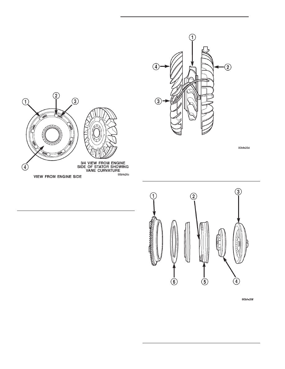
The stator assembly (Fig. 12) is mounted on a sta-
tionary shaft which is an integral part of the oil
pump. The stator is located between the impeller and
turbine within the torque converter case (Fig. 13).
The stator contains an over-running clutch, which
allows the stator to rotate only in a clockwise direc-
tion. When the stator is locked against the over-run-
ning clutch, the torque multiplication feature of the
torque converter is operational.
TORQUE CONVERTER CLUTCH (TCC)
The TCC (Fig. 14) was installed to improve the
efficiency of the torque converter that is lost to the
slippage of the fluid coupling. Although the fluid cou-
pling provides smooth, shock–free power transfer, it
is natural for all fluid couplings to slip. If the impel-
ler and turbine were mechanically locked together, a
zero slippage condition could be obtained. A hydraulic
piston was added to the turbine, and a friction mate-
rial was added to the inside of the front cover to pro-
vide this mechanical lock-up.
OPERATION
The converter impeller (Fig. 15) (driving member),
which is integral to the converter housing and bolted
to the engine drive plate, rotates at engine speed.
The converter turbine (driven member), which reacts
from fluid pressure generated by the impeller, rotates
and turns the transmission input shaft.
Fig. 12 Stator Components
1 – CAM (OUTER RACE)
2 – ROLLER
3 – SPRING
4 – INNER RACE
Fig. 13 Stator Location
1 – STATOR
2 – IMPELLER
3 – FLUID FLOW
4 – TURBINE
Fig. 14 Torque Converter Clutch (TCC)
1 – IMPELLER FRONT COVER
2 – THRUST WASHER ASSEMBLY
3 – IMPELLER
4 – STATOR
5 – TURBINE
6 – FRICTION DISC
21 - 14
42RE AUTOMATIC TRANSMISSION
WJ
DESCRIPTION AND OPERATION (Continued)