Jeep Grand Cherokee WJ. Manual - part 402
STEERING COLUMN
TABLE OF CONTENTS
page
page
DESCRIPTION AND OPERATION
STEERING COLUMN . . . . . . . . . . . . . . . . . . . . . . 26
REMOVAL AND INSTALLATION
STEERING COLUMN . . . . . . . . . . . . . . . . . . . . . . 26
SPECIFICATIONS
TORQUE CHART . . . . . . . . . . . . . . . . . . . . . . . . . 30
SPECIAL TOOLS
STEERING COLUMN . . . . . . . . . . . . . . . . . . . . . . 30
DESCRIPTION AND OPERATION
STEERING COLUMN
DESCRIPTION
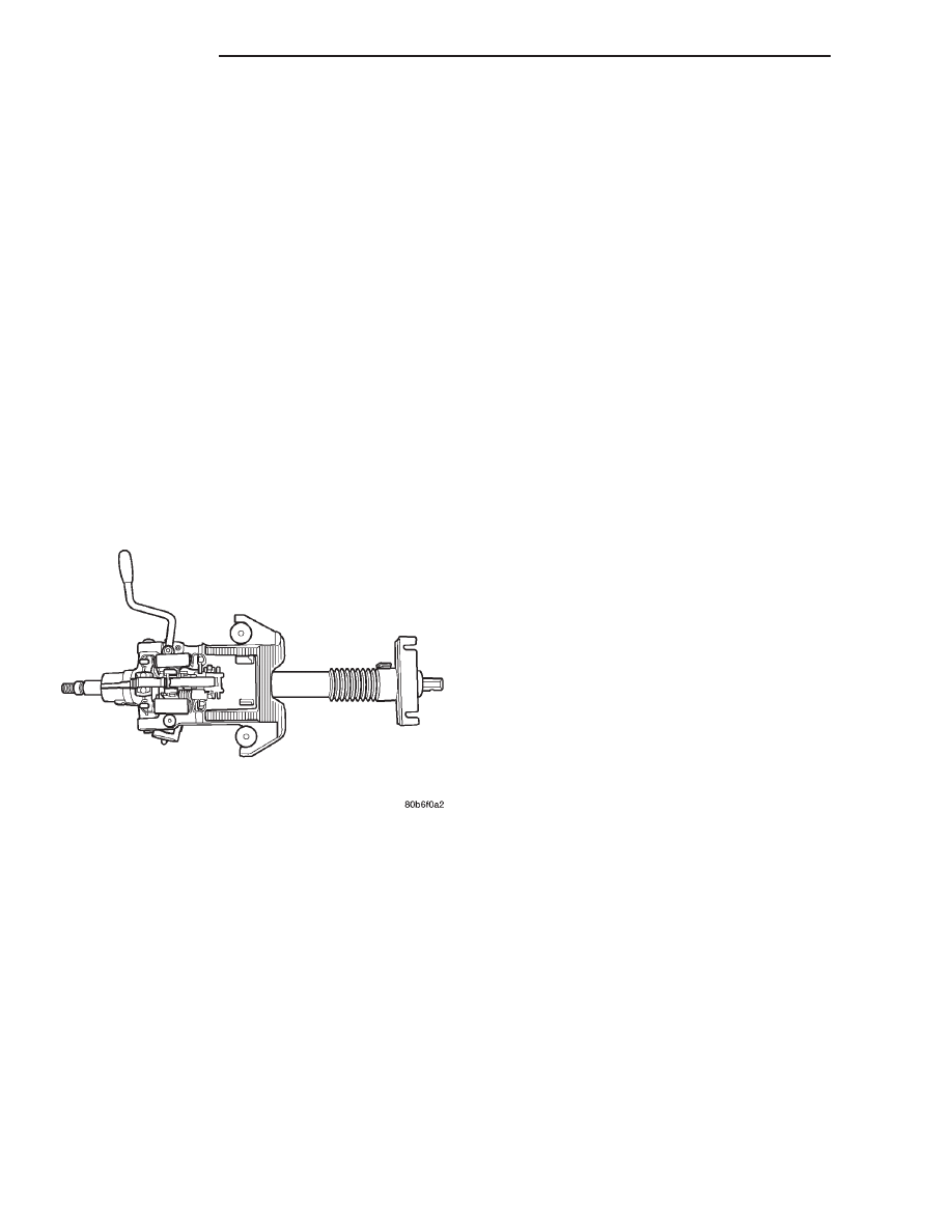
The tilt column (Fig. 1) has been designed to be
serviced as an assembly, less the wiring, switches,
shrouds, steering wheel, etc. Most steering column
components can be serviced without removing the
steering column from the vehicle.
SERVICE WARNINGS AND CAUTIONS
To service the steering wheel, switches or airbag,
refer to Group 8M and follow all WARNINGS and
CAUTIONS.
WARNING: THE AIRBAG SYSTEM IS A SENSITIVE,
COMPLEX ELECTRO-MECHANICAL UNIT. BEFORE
ATTEMPTING TO DIAGNOSE, REMOVE OR INSTALL
THE AIRBAG SYSTEM COMPONENTS YOU MUST
FIRST DISCONNECT AND ISOLATE THE BATTERY
NEGATIVE (GROUND) CABLE. THEN WAIT TWO
MINUTES FOR THE SYSTEM CAPACITOR TO DIS-
CHARGE. FAILURE TO DO SO COULD RESULT IN
ACCIDENTAL DEPLOYMENT OF THE AIRBAG AND
POSSIBLE PERSONAL INJURY. THE FASTENERS,
SCREWS, AND BOLTS, ORIGINALLY USED FOR
THE AIRBAG COMPONENTS, HAVE SPECIAL COAT-
INGS AND ARE SPECIFICALLY DESIGNED FOR THE
AIRBAG
SYSTEM.
THEY
MUST
NEVER
BE
REPLACED WITH ANY SUBSTITUTES. ANYTIME A
NEW FASTENER IS NEEDED, REPLACE WITH THE
CORRECT FASTENERS PROVIDED IN THE SERVICE
PACKAGE OR FASTENERS LISTED IN THE PARTS
BOOKS.
CAUTION: Safety goggles should be worn at all
times when working on steering columns.
REMOVAL AND INSTALLATION
STEERING COLUMN
WARNING: BEFORE SERVICING THE STEERING
COLUMN THE AIRBAG SYSTEM MUST BE DIS-
ARMED. FAILURE TO DO SO MAY RESULT IN ACCI-
DENTAL
DEPLOYMENT
OF
THE
AIRBAG
AND
POSSIBLE PERSONAL INJURY. REFER TO GROUP
8M RESTRAINT SYSTEMS FOR SERVICE PROCE-
DURES.
REMOVAL
(1) Position front wheels straight ahead.
(2) Disconnect and isolate the negative (ground)
cable from the battery.
(3) Remove
the
airbag,
refer
to
Group
8M
Restraint Systems for service procedures.
(4) Remove the steering wheel nut and remove
wheel with Puller C-3894-A (Fig. 2).
NOTE: Ensure the puller jaws are seated in the
pockets (Fig. 3) of the steering wheel armature.
(5) Remove the cluster bezel by pulling it from the
instrument panel (Fig. 4).
(6) Remove the knee blocker cover (Fig. 5), refer to
Group 8E Instrument Panel Systems.
(7) Remove the lower steering column shroud
mounting screw (Fig. 6).
Fig. 1 Steering Column
19 - 26
STEERING
WJ