Jeep Grand Cherokee WJ. Manual - part 161


  Index      Jeep     Jeep Grand Cherokee WJ - service repair manual 2001 year


Search            


Content   ..  159  160  161  162   ..


Jeep Grand Cherokee WJ. Manual - part 161


Track Adjuster in the Removal and Installation sec-
tion of Group 23 - Body for the procedures.

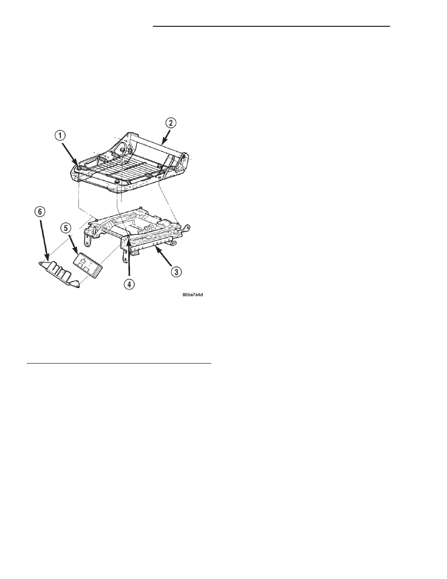
(3) Lift the memory seat module and its mounting

bracket off of the two forward studs on the upper
mounting rails of the power seat track and move the
unit away from the seat far enough to access the
power seat wire harness connectors (Fig. 2).

(4) Disconnect the two power seat wire harness

connectors from the memory seat module connector
receptacles.

(5) There are two snap clips that are molded into

the lower side of the memory seat module which help
to secure the module to the riser portion of the
stepped mounting bracket. Using a trim stick or
another suitable wide flat-bladed tool, gently pry
each of the two snap clips while pulling the module
away from the mounting bracket.

(6) Slide the memory seat module off of the two

mounting bracket slide tabs.

INSTALLATION

(1) Slide the memory seat module onto the two

mounting bracket slide tabs. Be certain that the two
snap clips that are molded into the lower side of the
memory seat module are fully engaged in the holes
in riser portion of the stepped mounting bracket.

(2) Position the memory seat module and mount-

ing bracket unit to the front of the power seat track
unit.

(3) Reconnect the two power seat wire harness

connectors to the memory seat module connector
receptacles.

(4) Position the memory seat module mounting

bracket over the two forward studs on the upper
mounting rails of the power seat track.

(5) Install the driver side front bucket seat onto

the power seat track unit. Refer to Bucket Seat
Track Adjuster 
in the Removal and Installation sec-
tion of Group 23 - Body for the procedures.

(6) Reconnect the battery negative cable.

NOTE: Following installation, it will be necessary to
initialize the Memory Seat Module (MSM) or Memory
Heated Seat Module (MHSM). In order to function
properly, the MSM or MHSM must “learn” the sen-
sor values of each of the power seat motor position
transducers in each of the adjuster hard stop posi-
tions. This is done by performing the “Reset Guard
Band” procedure using a DRB scan tool and the
proper Diagnostic Procedures manual.

WARNING: THE “RESET GUARD BAND” PROCE-
DURE WILL CAUSE THE DRIVER SIDE FRONT
SEAT TO AUTOMATICALLY ADJUST TO EACH OF
ITS TRAVEL LIMITS. BE CERTAIN THAT NO ONE IS
SEATED IN THE VEHICLE AND THAT THERE IS
NOTHING IN THE VEHICLE THAT WILL OBSTRUCT
SEAT MOVEMENT. FAILURE TO OBSERVE THIS
WARNING COULD RESULT IN PERSONAL INJURIES
AND/OR VEHICLE DAMAGE.

MEMORY SWITCH

REMOVAL

(1) Disconnect and isolate the battery negative

cable.

(2) Remove the trim panel from the driver side

front door. Refer to Front Door Trim Panel in the
Removal and Installation section of Group 23 - Body
for the procedures.

(3) Disconnect the memory switch wire harness

connector from the driver door module connector
receptacle.

(4) Remove the two screws that secure the memory

switch to the back of the driver side front door trim
panel.

(5) Remove the memory switch from the back of

the driver side front door trim panel.

Fig. 2 Memory Seat Module Remove/Install

1 – NUT (4)
2 – SEAT CUSHION FRAME
3 – POWER SEAT TRACK
4 – STUD (4)
5 – MODULE
6 – BRACKET

8R - 14

POWER SEAT SYSTEMS

WJ

REMOVAL AND INSTALLATION (Continued)

INSTALLATION

(1) Position the memory switch onto the back of

the driver side front door trim panel.

(2) Install and tighten the two screws that secure

the memory switch to the back of the driver side
front door trim panel. Tighten the screws to 2.2 N·m
(20 in. lbs.).

(3) Reconnect the memory switch wire harness

connector to the driver door module connector recep-
tacle.

(4) Install the trim panel onto the driver side front

door. Refer to Front Door Trim Panel in the
Removal and Installation section of Group 23 - Body
for the procedures.

(5) Reconnect the battery negative cable.

WJ

POWER SEAT SYSTEMS

8R - 15

REMOVAL AND INSTALLATION (Continued)

POWER WINDOW SYSTEMS

TABLE OF CONTENTS

page

page

DESCRIPTION AND OPERATION

POWER WINDOW SYSTEM . . . . . . . . . . . . . . . . . 1
POWER WINDOW MOTOR. . . . . . . . . . . . . . . . . . 2
POWER WINDOW SWITCH . . . . . . . . . . . . . . . . . 2

DIAGNOSIS AND TESTING

POWER WINDOW SYSTEM . . . . . . . . . . . . . . . . . 3

POWER WINDOW MOTOR. . . . . . . . . . . . . . . . . . 5
REAR DOOR POWER WINDOW SWITCH . . . . . . 5

REMOVAL AND INSTALLATION

POWER WINDOW MOTOR. . . . . . . . . . . . . . . . . . 6
REAR DOOR POWER WINDOW SWITCH . . . . . . 6

DESCRIPTION AND OPERATION

POWER WINDOW SYSTEM

DESCRIPTION

Power operated driver side and passenger side

front and rear door windows are standard factory-in-
stalled equipment on this model. The power window
system allows each of the door windows to be raised
or lowered electrically by operating a switch on the
trim panel for that door. Additionally, the master
switches on the driver side front door trim panel
allow of the windows to be operated from the driver
seat position. A power window lockout switch on the
driver side front door trim panel will allow the driver
to disable all of the passenger door window switches.

The power window system operates on ignition

switched battery current supplied through a fuse in
the junction block, only when the ignition switch is
in the On position. However, a unique feature of this
system will allow the power windows to be operated
for up to forty-five seconds after the ignition switch
is turned to the Off position, or until a front door is
opened, whichever occurs first.

An auto-down feature allows the driver side front

door window to be lowered all the way, even if the
window switch is released. The driver side front door
window switch must be depressed in the down direc-
tion to a second detent to begin an auto-down event.
Depressing the switch again in any direction will
stop the window movement and cancel the auto-down
event.

This group covers the following components of the

power window system:

• Power window switches

• Power window motors.
Certain functions and features of the power win-

dow system rely upon resources shared with other
electronic modules in the vehicle over the Program-
mable Communications Interface (PCI) data bus net-

work. The PCI data bus network allows the sharing
of sensor information. This helps to reduce wire har-
ness complexity, internal controller hardware, and
component sensor current loads. At the same time,
this system provides increased reliability, enhanced
diagnostics, and allows the addition of many new fea-
ture capabilities. For diagnosis of these electronic
modules or of the PCI data bus network, the use of a
DRB scan tool and the proper Diagnostic Procedures
manual are recommended.

The other electronic modules that may affect power

window system operation are as follows:

• Body Control Module (BCM) - Refer to Body

Control Module in the Description and Operation
section of Group 8E - Instrument Panel Systems for
more information.

• Driver Door Module (DDM) - Refer to Door

Module in the Power Lock System section of Group
8P - Power Lock Systems for more information.

• Passenger Door Module (PDM) - Refer to

Door Module in the Power Lock System section of
Group 8P - Power Lock Systems for more informa-
tion.

This group covers diagnosis and service of only the

electrical components in the power window system.
For service of mechanical components, such as the
regulator, lift plate, window tracks, or glass refer to
Group 23 - Body. Refer to Power Windows in the
Contents of Group 8W - Wiring Diagrams for com-
plete circuit diagrams. Following are general descrip-
tions of the major components in the power window
system.

OPERATION

The power window system includes the Driver

Door Module (DDM) and Passenger Door Module
(PDM), which are mounted in their respective front
door, the rear door power window switches mounted
on the rear doors, and the power window motors
mounted to the window regulator in each door. The
DDM houses four master power window switches, the

WJ

POWER WINDOW SYSTEMS

8S - 1


Content   ..  159  160  161  162   ..