Jeep Grand Cherokee WJ. Manual - part 104
(4) Work around the perimeter of the cluster hous-
ing to disengage each of the eight latches that secure
the cluster lens, hood and mask unit to the cluster
housing (Fig. 12).
(5) Gently pull the cluster lens, hood and mask
unit away from the cluster housing.
CLUSTER HOUSING REAR COVER
(1) Disconnect and isolate the battery negative
cable.
(2) Remove the instrument cluster from the instru-
ment panel. Refer to Instrument Cluster in the
Removal and Installation section of this group for the
procedures.
(3) Remove the seven screws that secure the rear
cover to the back of the cluster housing (Fig. 13).
(4) Disengage the latches (two on top, four on the
bottom) that secure the upper and lower edges of the
rear cover to the top and bottom of the cluster hous-
ing.
(5) Remove the rear cover from the back of the
cluster housing.
GAUGE
(1) Disconnect and isolate the battery negative
cable.
(2) Remove the knob from the trip odometer reset
switch stem. Refer to Instrument Cluster Compo-
nents - Trip Odometer Reset Knob in the
Removal and Installation section of this group for the
procedures.
(3) Remove the instrument cluster from the instru-
ment panel. Refer to Instrument Cluster in the
Removal and Installation section of this group for the
procedures.
(4) Remove the cluster lens, hood and mask unit
from the cluster housing. Refer to Instrument Clus-
ter Components - Cluster Lens, Hood and Mask
in the Removal and Installation section of this group
for the procedures.
(5) Remove the rear cover from the cluster hous-
ing. Refer to Instrument Cluster Components -
Cluster Housing Rear Cover in the Removal and
Installation section of this group for the procedures.
(6) From the rear of the cluster housing, carefully
straighten the small metal mounting tabs (two for
each major gauge, and four for each minor gauge set)
that secure the gauge or gauge set to the cluster elec-
tronic circuit board (Fig. 13).
(7) From the front of the cluster housing, carefully
pull the gauge or gauge set straight out of the gauge
mounting cavity(ies) in the cluster housing.
CLUSTER HOUSING
(1) Disconnect and isolate the battery negative
cable.
(2) Remove the knob from the trip odometer reset
switch stem. Refer to Instrument Cluster Compo-
nents - Trip Odometer Reset Knob in the
Removal and Installation section of this group for the
procedures.
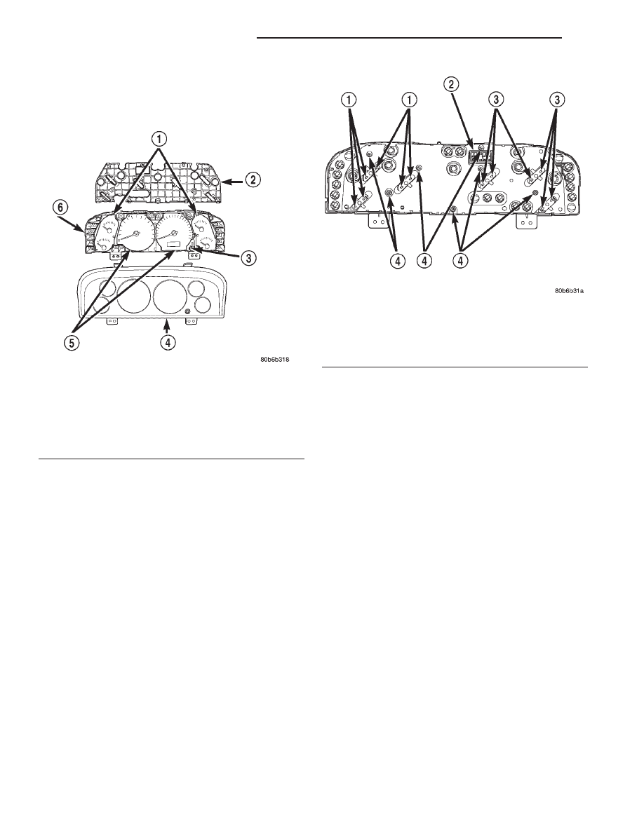
Fig. 12 Instrument Cluster Components
1 – GAUGE SETS
2 – REAR COVER
3 – TRIP ODOMETER RESET KNOB
4 – LENS, HOOD AND MASK
5 – GAUGES
6 – CLUSTER HOUSING
Fig. 13 Cluster Housing Rear Cover Screws
1 – GAUGE MOUNTING TABS
2 – CONNECTOR RECEPTACLE
3 – GAUGE MOUNTING TABS
4 – REAR COVER SCREWS (7)
8E - 18
INSTRUMENT PANEL SYSTEMS
WJ
REMOVAL AND INSTALLATION (Continued)