Jaguar AJV8 engine / 5HP24 transmission. Manual - part 8


  Index      Jaguar     Jaguar AJV8 engine / 5HP24 transmission - service repair manual 1996 year


Search            


Content   ..  6  7  8  9   ..


Jaguar AJV8 engine / 5HP24 transmission. Manual - part 8


Engine

AJ-V8/5HP24

33

Fuel System

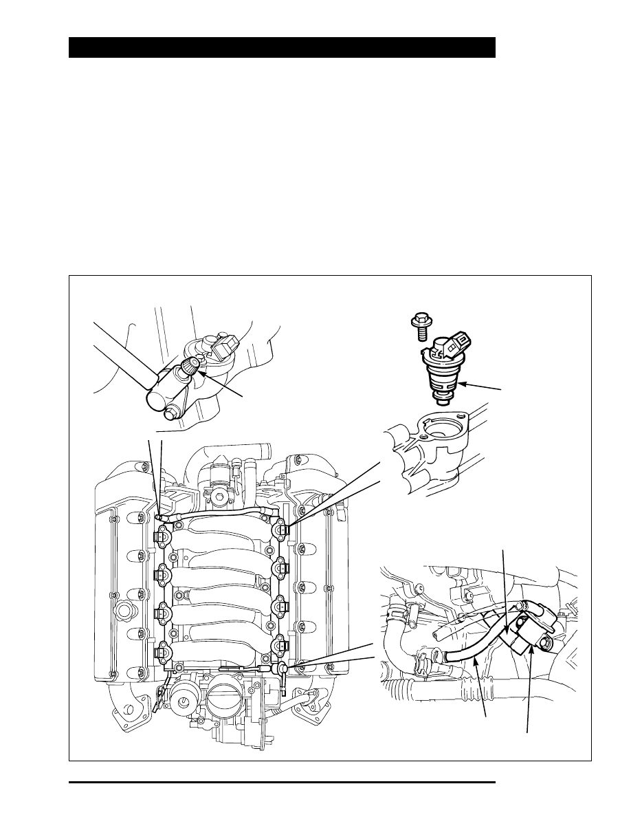
Fuel injectors, controlled by the ECM, are
installed in the fuel rails on each side of the
intake manifold. A cross-over pipe connects the
two fuel rails together at the front of the
manifold. A test valve in the cross-over pipe
allows the fuel rail to be pressurised and
depressurised during servicing and
troubleshooting.
A pressure regulator on the rear of the right fuel
rail controls the pressure in the fuel rails.
A return line directs excess fuel from the
pressure regulator back to the fuel tank.

FUEL SYSTEM

Test Valve

Fuel Injector

Fuel Return

Intake Manifold Pressure

Fuel Pressure Regulator

303-024/059/078/155

Engine

AJ-V8/5HP24

34

Fuel Injectors

Eight, side fed, dual straight jet, fuel injectors are
installed in the fuel rails. The injectors are
electromagnetic solenoid valves controlled by the
ECM. Two O-rings seal each injector to manifold
interface. The fuel jets from the injectors are
directed onto the back of the intake valves.

Pressure Regulator

The pressure regulator is a diaphragm operated
valve that regulates fuel rail pressure at 2.9 bar
(42.05 psi) above intake manifold pressure.

FUEL INJECTOR

303-025

Engine

AJ-V8/5HP24

35

Ignition System

The ignition system consists of two ECM
controlled ignition amplifier modules, which each
supply four spark plug mounted ignition coils.
The 14 mm spark plugs, one per cylinder, locate
in recesses down the center-line of each cylinder
head.
The on-plug ignition coils are secured to the
camshaft covers. The engine harness connects
the on-plug ignition coils to the ignition amplifiers
located on the vehicle body. A composite cover
fits over the on-plug coils.

Crankcase Ventilation

The engine is ventilated through a part load and a
full load breather.
The part load breather is a flexible composite
hose connected between the oil separator in B
bank camshaft cover and the induction elbow. A
restrictor in the outlet from the oil separator
prevents reverse flow.
The full load breather is a flexible composite hose
connected between the oil separator in A bank
camshaft cover and the air intake duct.
The ends of the breather hoses incorporate quick
release connectors (see figure, page 36).
The oil separators consist of wire gauze packed
into an open ended enclosure below the breather
outlet.

IGNITION COIL AND SPARK PLUG

303-049

OIL SEPARATOR

303-046

Engine

AJ-V8/5HP24

36

CRANKCASE VENTILATION  SYSTEM

Part Load Breather Hose Connector

Full Load Breather Hose Connector

303-065/077/079


Content   ..  6  7  8  9   ..