Jaguar XJ (X350). Manual - part 941
-> Yes
REPAIR the high resistance circuit. For additional information, refer to the wiring diagrams. CLEAR the
DTC. TEST the system for normal operation.
-> No
INSTALL a new catalyst monitor sensor.
Catalyst Monitor Sensor (18.30.66) CLEAR the DTC. TEST the system for normal operation.
PINPOINT TEST G531332p9 : RIGHT-
HAND CATALYST MONITOR SENSOR
HEATER CONTROL CIRCUIT
LOW/HIGH RESISTANCE
G531332t31 : CHECK THE POWER SUPPLY TO THE CATALYST MONITOR
HEATER
1. Key off. 2. Disconnect the catalyst monitor sensor electrical connector, PI11. 3. Key on, engine off.
4. Make sure the O2S heater relay is engaged. 5. Measure the voltage between:
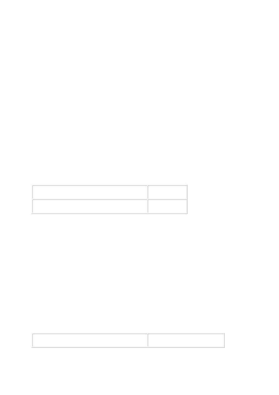
Catalyst monitor sensor connector PI11, harness side
Battery
Pin 02
Negative terminal
Is the voltage greater than 10 volts?
-> Yes
GO to Pinpoint Test G531332t32.
-> No
REPAIR the power supply circuit to the catalyst monitor sensor heater. This circuit includes the heater
relay and fuse 33 of the front power distribution box. For additional information, refer to the wiring
diagrams. CLEAR the DTC. TEST the system for normal operation.
G531332t32 : CHECK THE CATALYST MONITOR HEATER CONTROL CIRCUIT
FOR HIGH RESISTANCE
1. Key off. 2. Disconnect the ECM electrical connector, PI300. 3. Measure the resistance between:
Catalyst monitor sensor connector PI11, harness side ECM connector PI300, harness side