Jaguar XJ (X350). Manual - part 516
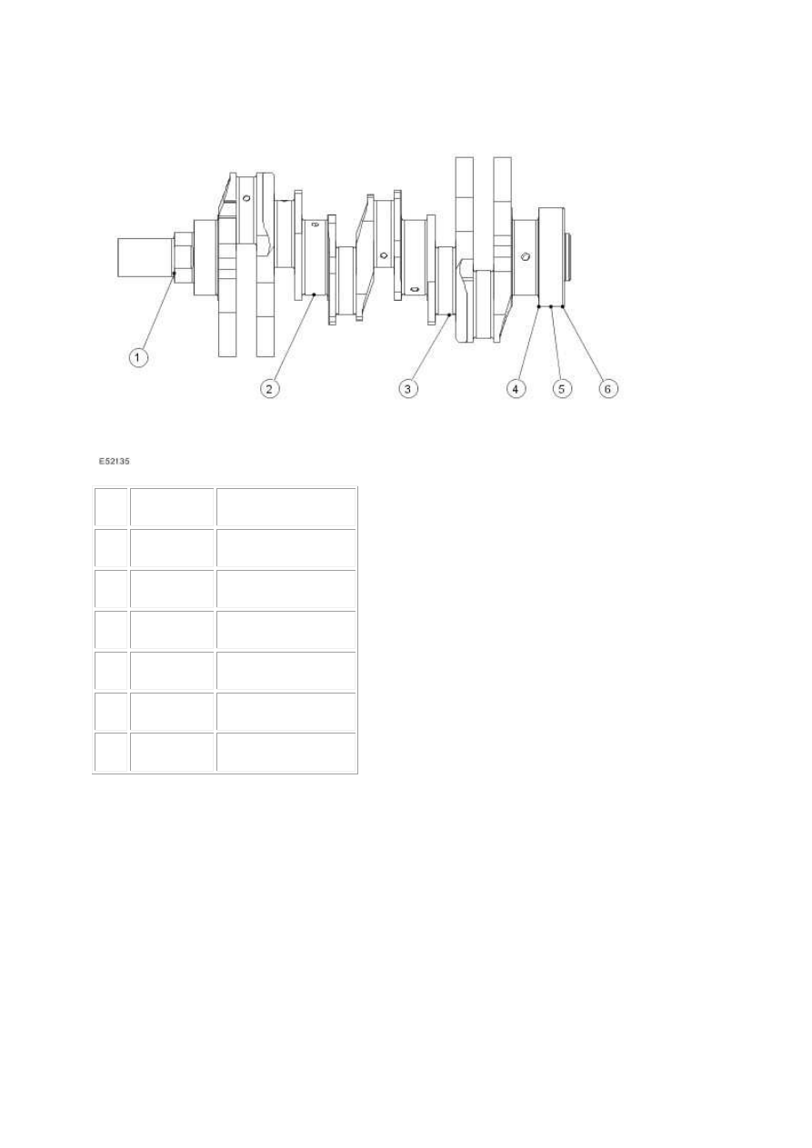
Crankshaft
Item
Part Number
Description
1
—
Oil pump drive
2
—
Main bearing journal
3
—
Big end journal
4
—
Rear drive flange
5
Rear oil seal location
6
Trigger wheel location
The crankshaft is forged steel and fillet rolled with induction hardened journals, which run in four
bearings with clamped two layer bearing shells. The upper and lower shells of bearing number four
are flanged, which limits the end float of the crankshaft. The main bearing caps are double bolted
and cross bolted to increase the strength and rigidity of the engine block.
The rear main oil seal and retainer assembly is a one piece unit and is supplied with its own plastic
fitting sleeve. The seal and retainer have two locating dowels and ten fixing bolts. In addition the
retainer has a location for the crankshaft position sensor.
A torsional vibration crankshaft damper pulley is bolted to the front of the crankshaft.
The crankshaft trigger wheel is located on the rear of the crankshaft. It is pressed onto the crank