JAC S2. Engine. Service Manual - part 2


  Index      JAC     JAC S2. Engine. Service Manual


Search            copyright infringement  


Content      ..      1      2      3      ..


JAC S2. Engine. Service Manual - part 2


Engine Mechanical System


Engine Mechanical System                                                                                                                                                          17 
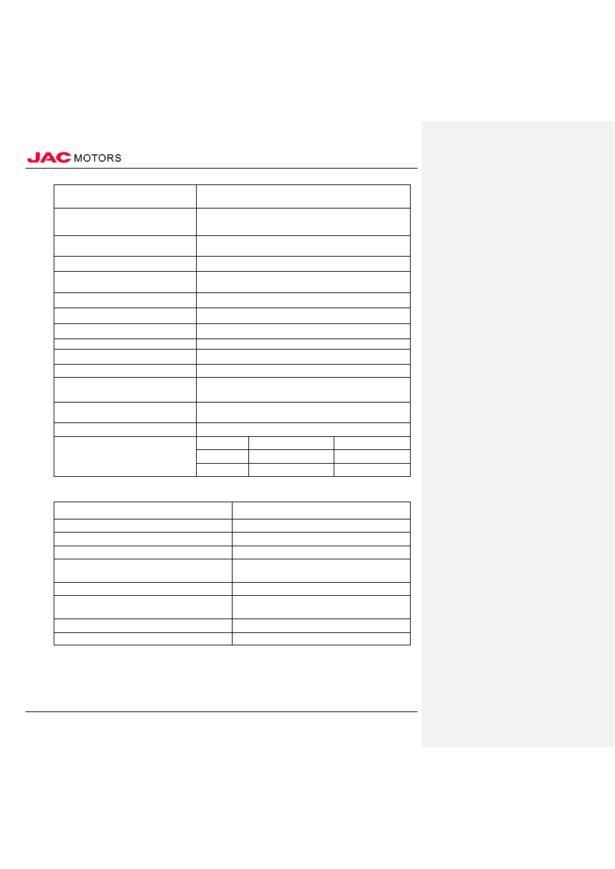
 

type 

HFC4GB2
.3D 

Max torque(N·m) 

1
4

Max torque  r pm(r/min) 

3500~4
500 

idle (r/min) 

750
±30 

full load min fuel consumption (g/kw.h) 

2
4

engine oil consumption ratio at rated power 

                                          ≤ 0.15% 

crankshaft rotation direction(facing power output )                                    anticlockwise 

Starting method 

                        Electric starting 

Lubrication method 

      Mixed Type of pressure and spatter 

Cooling method 

Water cooling 

New engine oil filling volume (L) 

4
.

Outside dimension  ( length × width× hight )mm 

560×543×608 

Net weight (kg) 

8

Fuel type 

93#  and above 


Engine oil type 

Engine oil type 

Environment temperature 

Quality degree 

SAE 5W/30 

-30 ℃~ 30 ℃ 

SJ  and above 

SAE 15W/40 

-20 ℃~ 40 ℃ 

SJ  and above 


Main parts specs 


Part name 

Technical characteristics 

Engine oil filter 

full flow type filter thread specs M20×1.5-6H 

oil pump 

Inner meshing rotors type 

cooling water pump 

centrifugal 

Thermostat 


wax type, initial temperature:82 ℃ ; full open temperature:95 ℃ 

Generator  

Built-in regulator alternator specs  14V 90A 

starter 

Permanent magnet decelerating type starting  voltage  12V,  power 
1.2kW 

ignition plug 

Iridium platinum alloy type 

Oil pressure guide rail 

No oil back 


-------------------------------------------------------------------------------------------------------------------------------------------------------------


Engine Mechanical System


Engine Mechanical System                                                                                                                                                          18 


items 

Standard value 

Extreme rate 

camshaft 


Camshaft height (mm) 

Air intake 

44.7054±0.1mm 


Air exhaust 

44.2836±0.1mm 


Cylinder cover and valve 

Cylinder pad surface flatness (mm) 

Under 0.03  

0.1 

Cylinder cover whole height (mm) 

112.9 

~ 113.1 


-------------------------------------------------------------------------------------------------------------------------------------------------------------


Engine Mechanical System


Engine Mechanical System                                                                                                                                                          19 


Items  

Standard value 

Extreme rate 


valve edge thickness (mm) 

Intake valve 

1.35 

0.85 

Intake valve 

1.85 

1.35 

valve stem diameter (mm) 

φ5.5 


clearance between the valve guide and valve 
stem (mm) 

Intake


0.020 

~ 0.036 

0.10 

Intake


0.030 

~ 0.045 

0.15 

Valve taper angle 

45° 

~ 45.5° 


Valve length (mm) 

Intake valve


89.61 

89.11 

Intake valve


90.94 

90.44 

Valve spring free height(mm) 

43.1 

42.7 


Valve spring load /installation height (N)/ (mm) 

152/33.4 


310/25.2 


Valve springs verticality 

小于 2° 

4° 

Contact  width of the valve seat(mm) 

0.9 

~ 1.3 


valve guide inner diameter(mm) 

φ5.5 


Valve guide projection amont (mm) 

13±0.3 


Oil pump gear tip clearance (mm) 

0.06 

~ 0.18 

0.2 

Oil pump side clearance (mm) 

0.04 

~ 0.11 

0.15 

Oil pump shell clearance (mm) 

0.10 

~ 0.18 

0.2 

Piston skirt diameter(mm) 

74.968 

~ 74.978 


Top compression ring side clearance (mm) 

0.03 

~ 0.07 

0.10 

Second compression ring side clearance (mm) 

0.02 

~ 0.06 

0.1 

Top compression ring opening clearance(mm) 

0.15 

~ 0.30 

0.8 

Second compression ring opening clearance (mm) 

0.30 

~ 0.50 

0.8 

compound oil ring opening clearance (mm) 

0.20 

~ 0.50 

1.0 

piston pin outer diameter(mm) 

18.002 

~ 18.005 


Connecting rod journal clearance (mm) 

0.02 

~ 0.04 

0.1 

Connecting rod


big head clearance (mm) 

0.10 

~ 0.25 

0.4 

Crankshaft axial clearance(mm) 

0.09 

~ 0.27 


crankshaft main journal diameter (mm) 

46.004 

~ 46.029 


Connecting journal diameter (mm) 

39.982 

~ 40.0 


crankshaft main journal neck clearance (mm) 

0.02 

~ 0.04 


Cylinder pad surface flatness (mm) 

0.03 

以下 


Cylinder total height(mm) 

280 


Cylinder cylindricity (mm) 

0.007 


bore inside diameter (mm) 

75.000 

~ 75.015 


Clearance between the piston and cylinder (mm) 

0.02 

~ 0.04 


-------------------------------------------------------------------------------------------------------------------------------------------------------------


Engine Mechanical System


Engine Mechanical System                                                                                                                                                          20 


Main inspection and adjustment parameters 


Valve clearance (mm) 

Intake valve 0.22±0.03 

exhaust valve0.30±0.03 

emission standard 

               euro

  V 

Oil pressure 

Idle oil pressure >100kPa 

Oil temperature 

≤ 135 ℃ 

Water temperature 

≤ 110 ℃ 

Spark plug electrode clearance 

0.7 

~ 0.8mm 


Sealant 


Seal location 

No.  Sealant 

 
Crankshaft rear oil seal component - body 

1  DowCorning 3-0115 Gasket sealant adhesive 

2  Threebond 1217G 

3  Ksetra-ksetrajna new 1590 


oil sump - engine body - Crankshaft rear oil seal 
component 

4  DowCorning 3-0115 Gasket sealant adhesive 

5  Threebond 1217G 

6  Ksetra-ksetrajna new 1590 


Sprocket wheel cover –engine  body –cylinder 
cover 

7  DowCorning 3-0115 Gasket sealant adhesive 

8  Threebond 1217G 

9  Ksetra-ksetrajna new 1590 

Bowl type plug - cylinder cover 

10  Loctite 12086  bowl type plug sealant 

Crankshaft signal wheel bolt 

11  Loctite 262 threaded fastening adhesive 

water temperature sensor 

12  Ksetra-ksetrajna new  1243


thread

 sealant


oil pressure switch 

13  Ksetra-ksetrajna new  1243


thread

 sealant


Lubricant 


Engine oil type 

Environment Temperature  

Quality degree 

SAE 5W/30 

-30 ℃~ 30 ℃ 

SJ  and abve 

SAE 15W/40 

-20 ℃~ 40 ℃ 

SJ  and abve 


(IV)Torque parameter 


Key parts torque table 

No. 

item 

torque  (N·m) 

remark 

Main bearing cap bolt 

(35±2)N·

m+60° 

~ 64° 

M9×1.25×74.5 


connecting rod bolt 

5N·

m → 10N·

m → 

13N·

m+45°+45° 


M6×0.75×33 

The camshaft bearing cover bolts 

11±1 

M6×1×35 

The camshaft front end bearing cap bolts 

20±1 

M8×1.25×30 

-------------------------------------------------------------------------------------------------------------------------------------------------------------


Engine Mechanical System


Engine Mechanical System                                                                                                                                                          21 


No. 

item 

torque  (N·m) 

remark 


Cylinder cap bolt 

(24.5±2)N·

m+180° 

~ 

184° 


M9×1.25×143.5 

The crankshaft pulley bolt 

(50±2)N·

m+(60±2)° 

M14×1.5×54 

Flywheel bolt 

100±5 

M11×1.25×25 

Exhaust camshaft sprocket bolt 

88±10 

M12×

30 

Valve timing adjuster bolt 

70±5 

M10×

41 

10 

Crankshaft rear oil seal bolt 

7.6±0.6 

M6×10 E8 

11 

Rear ear stud 

18.4±1.4 

M8×20 E10 

12 

Intake manifold bolt 

18±1.0 

M8×40 E10 

13 

Oil sump bolts 

11±1.0 

M6×12 E8 

14 

Sprocket cover boltsⅠ 

39.5±3.0 

M10×90 E14 

15 

Sprocket cover boltsⅡ 

39.5±3.0 

M10×50 E14 

16 

Sprocket cover boltsⅢ 

8.4±0.6 

M6×30 E10 

17 

M6×20 E10  type bolt 

8.4±0.6 

M6×20 E10 

18 

M6×12 E10  type bolt 

8.4±0.6 

M6×12 E10 

19 

M6×45 E10  type bolt 

8.4±0.6 

M6×45 E10 

20 

M6×25 E10  type bolt 

8.4±0.6 

M6×25 E10 

21 

M6×12 E8  type bolt 

8.4±0.6 

M6×12 E8 

22 

Cylinder head cover bolt 

9±1.0 

M6×27 E10 

23 

Oil filter Bracket bolt 

20±1 

M8×30 E12 

24 

Warm wind backwater pipe bolt 

7.6±0.6 

M6×20 E8 

25 

Oil pressure guide rail bolt 

18.4±1.4 

M8×35 E12 

26 

Main oil passage cloggingⅠ 

60±5 

内 VI 角 M20 

27 

Main oil passage cloggingⅡ 

35±5 

内 VI 角 M12 

28 

drain screw 

25±5 

内 VI 角 M12 

29 

oil passage clogging 

20±2 

内 VI 角 M10 

30 

VVT  oil passage clogging 

44±5 

M14×1.5×14 

31 

Oil drain plug 

39±5 

M14×1.5×14 

32 

Fixed rail bolt components 

10±2 

M6×1×1

33 

Moving rail bolt components 

23.5±4.5 

M8×1.25×15 

34 

Starter bolt 

24±3 

M8×

55 

35 

oil pressure switch 

10±2 

1/8 

36 

Spark plug 

25 

~ 30 

M

1

37 

Exhaust manifold double-headed stud 

12±2 

M8×1×1

38 

Q1840816(Exhaust manifold bracket bolts ) 

20 

~ 25 

M8×

16 

39 

Catalysts insulation cap nut 

10±1 

M6

×1 

40 

The crankshaft signal wheel bolt 

12.5±2.5 

M

-------------------------------------------------------------------------------------------------------------------------------------------------------------


Engine Mechanical System


Engine Mechanical System                                                                                                                                                          22 

41 

water temperature sensor 

20±4 


-------------------------------------------------------------------------------------------------------------------------------------------------------------


Engine Mechanical System


Engine Mechanical System                                                                                                                                                          23 


No. 

Item 

Torque  (N·m) 

remark 

42 

Hall sensor bolt 

8~10 

Inner six flower  M6×1×16 

43 

knock sensor bolts 

20±4 

Inner six flower M8×1.25×30 

44 

Exhaust manifold nut 

35±2 

M8 

45 

Throttle self-drilling bolt 

8~10 

Inner six flower M6×1×25 

46 

square-head bolt 

47±5 

M10×1.25×90 

47 

idle pulley bolt 

49±9 

M10×1.25×38 


48 


Oil filter 

After Installation surface contact, 
rotate  3/4 rounds or 

(11±1) N·m 


49 

idle pulley assembly 

50±5 

M10×1.5 


Standard component torque 


No. 

item 

torque(N·m) 

remark 

M6 

~ 11 


M8 

20 

~ 25 


M10 

30 

~ 50 


M12 

60 

~ 80 


(V)Precautions of maintenance 


general precautions 

1.  Precautions of exhausting engine coolant 

1).  Exhaust engine coolant after engine cools off. 

2.  Precautions of disconnecting fuel pipe 

1). Make sure there is no matters that could trigger spark or fire before working. 

2).  Release fuel pressure before disconnecting and dissolving. 

3).  After disconnecting pipe, gag the opening in case fuel will leak. 

3.  Precautions of removing and disassembly. 

1).  Please use special maintenance tools when it is required.  Be safe, do not disobey the 

instructions. 

2).  Be careful enough not to damage the matching surface and sliding suface. 

3).  If necessary, gag the opening of engine system with adhesive tape or something similar in case 

foreign matters will get inside. 

-------------------------------------------------------------------------------------------------------------------------------------------------------------


Engine Mechanical System


Engine Mechanical System                                                                                                                                                          24 

4).  Label and tidy the dissolved components in order, which is helpful to troubleshoot and 

reassembly. 

5).  The basic principle of loosening nut and screw is: loosen the outer ones first, then those on 

the diagonal, and so on. Please follow the appointed order if it is instructed. 

4.  Precautions of inspection /maintenance and replacement 

1). Check the components thoroughly before maintenance or replacement. Please replace if 

necessary. 

5.  Precautions of assembly 

1).  Use torque wrench to tighten nut and screw. 

2).  The basic principle of tightening nut and screw is:  tighten the center ones first, then those on 

the diagonal, with the same force. Please follow the appointed order if it is instructed. 

3).  Replace new pad, oil seal or “O”type ring. 

4).  Wash, clear and dry every component thoroughly. Check carefully if engine oil or coolant 

pipe is blocked. 

5).  Try not to damage sliding surface or matching surface, clear foreign matters like kerf or dust 

thoroughly. Smear sliding surface with engine oil before assembly. 

6).  When refill engine coolant after drilling, release air in the pipe.

-------------------------------------------------------------------------------------------------------------------------------------------------------------


Engine Mechanical System


Engine Mechanical System                                                                                                                                                          25 


7).  Start the engine and increase the rpm to check if there is leakage with engine coolant, fuel 

engine oil and intake/exhaust after maintenance. 

6.  Those parts need to be tightened with certain degree 

1).  Tighten the following engine parts finally with angle wrench: 

·Cylinder cap bolt 

· Main bearing cap bolt 

· Rod cap nut 

2).  Please do not tighten finally according to torque value. 

3).  Torque of these components is applicable for pre –tighten procedures. 

4).  Make sure the clear thread and base surface and smear engine oil 


Precautions of sealant 

1.  Remove sealant 

1).  After removing fixing nut and screws, separate matching surface with scraper and remove the 

old sealant. 

△Caution Be careful not to damage matching surface.  Insert scraper, and then knock side 

surface to slide as per the drawing. Please use rubber hammer knock component 

slightly to remove when it is hard to use scraper. Please be careful not to damage 

matching surface if it is unavoidable to use tools like screwdriver. 

2.  Employing procedures of sealant 

1).  Clear the old sealant sticked to the application surface and matching surface of gasket with 

scraper. 

△Caution Clear the old sealant thoroughly off the groove of application surface of sealant, fixed 

bolts and bolt hole. 

2).  Wipe the application surface and matching surface of sealant with unleaded gasoline, clear 

attached water, grease and foreign matter. 

3).  Put the sealant with appointed size at appointed place. 

△Caution     

。If  there is groove to put sealant, please put the sealant in the groove. Generally, 

-------------------------------------------------------------------------------------------------------------------------------------------------------------


Engine Mechanical System


Engine Mechanical System                                                                                                                                                          26 

put the sealant into the inner side of bolt hole, occasionally, outside, for the bolt hole. Install 

and connect components within 5 mins after smear the sealant. Please clear the blot if there is 

blot on the sealant.  Please do not tighten again bolt and nut after installation. 

Refill engine oil and engine coolant 30 mins after installation 

△Caution Please operate according to the instruction if there is special instruction. 


(VI)Special tool 


No. 

Tool 

Outside figure 

Instruction 


fork clamp 


Fixed camshaft timing gear 


pin 


use with fork clamp 

-------------------------------------------------------------------------------------------------------------------------------------------------------------


Engine Mechanical System


Engine Mechanical System                                                                                                                                                          27 


No. 

Tool 

shape drawing 

Description 


The flywheel stop 


Fixed 

flywheel 


Valve spring 
compressor 


Compression valve spring 


Oxygen sensor sleeve 


Remove and install the oxygen sensor 


oil sump disassemble 
tool 


Disassemble oil sump 


Valve oil seal installer 


Install valveoil seal 


Crankshaft front oil 

seal guide 


Play the role of guiding when installing 
crankshaft front oil seal 


Crankshaft front oil 

seal installer 


Install engine crankshaft front oil seal 


10 


Crankshaft rear oil seal 

installer  


Install crankshaft rear oil seal 

-------------------------------------------------------------------------------------------------------------------------------------------------------------


Engine Mechanical System


Engine Mechanical System                                                                                                                                                          28 


No. 

Tool 

shape drawing 

Description 


11 


Piston pin location tool 


Install and disassembly piston pin 


12 


guide sleeve 


Use together with piston pin location tool  


-------------------------------------------------------------------------------------------------------------------------------------------------------------


Engine Mechanical System


Engine Mechanical System                                                                                                                                                          29 

II failure diagnosis 

(I)Diagnosis analysis table 


No.  Failure 

description 

Reason analysis 

Solution 


Starter does not 
rotate 

The connection of battery electrode becomes 
loose or battery is low 

tighten or charge 


circuit is disconnected 

check and repair 

Starter has damage 

Repair or change 


Spark plug does not 
ignite 

ground connection is poor 

repair 


Ignition coil damage 

change 

spark plug clearance is not appropriate or burnt  Adjust or change 

Electronic ignition system has fault 

Repair or change


failure in oil supply 
system  

gasoline pump is insufficient in oil supply 

Repair or change


Petrol hose and fuel filter clogging 

Clear  


Cylinder 
compression 
pressure decreases 

cylinder pad rupture 

replace 


Valve clearance adjustment is improper or 
damaged 

adjust/ repair or change 

piston/


piston ring/cylinder wear  

Repair or change 

valve seal is poor 

Repair 


underpower during 
running  

the adjustment between acceleration pedal and 
Throttle Valve is not appropriate 

Adjust 


cylinder compression pressure decreases 

1.  check if valve/spark plug/cylinder 

pad leaks 

2.  cylinder grind 

fuel supply not sufficient 

Adjust or repair 

air intake not sufficient 

check intake system 

exhaust clogging 

check exhaust system, and clear the 
carbon deposition 

spark plug clearance inappropriate or damaged  adjust or change 


There is combustion 
knock inside the 
engine 

bearing bush wear/ crankshaft  cam wearing 

Replace 


Crankshaft/connecting rod axial diameter and 
piston pin wear off greatly 

Replace or repair 

Piston ring damage 

change 

-------------------------------------------------------------------------------------------------------------------------------------------------------------


Engine Mechanical System


Engine Mechanical System                                                                                                                                                          30 

valve clearance is inappropriate 

Adjust 

crankshaft thrust clearance is too big  

Adjust 

-------------------------------------------------------------------------------------------------------------------------------------------------------------


Engine Mechanical System


Engine Mechanical System                                                                                                                                                          31 


No.  Failure description 

Reason analysis 

soluti

on 


engine overheating 

Thermostat failure 

Change 


generator belt(water pump belt ) tensile 
force not enough 

Adjust 

coolant not enough or water pipe block 

Supplement or clear 

Water pump clearance inappropriate or 
damaged 

Repair or replace 

Radiator is blocked by incrustation 

Repair or replace 

Engine oil not enough 

supplement 

oil circuit blocked or oil pump damaged 

clear or replace 

spark plug clearance inappropriate or there 
is carbon


deposition 

clear or adjust 

exhaust  pipe blocked 

tighten or clear  

cylinder pad damaged 

Replace  

clutch slide 

repair or replace 


Excessive consumption of 
engine oil 

valve oil seal wear or damaged 

Replace 


Valve and valve duct wear 

Replace


Oil ring wear or damaged 

Replace


piston ring is wrongly opened according to 
regulation 

Replace


cylinder pad damaged 

Replace


engine overheating

、inner pressure 

increase

、part of the engine oil drained 

out through exhaust exit 


check related parts and excluded 

oil return is not smooth in respiratory 
system of cylinder cover shield, leading 
engine oil goes into intake system through 
respiratory hose 


replace or clear cylinder cover 
shield 

-------------------------------------------------------------------------------------------------------------------------------------------------------------


Engine Mechanical System


Engine Mechanical System                                                                                                                                                          32 


(II)diagnose flow chart 


Engine overheating 


-------------------------------------------------------------------------------------------------------------------------------------------------------------


Content      ..      1      2      3      ..