Iveco EuroCargo (12 to 26 t). Manual - part 162
77844
Description
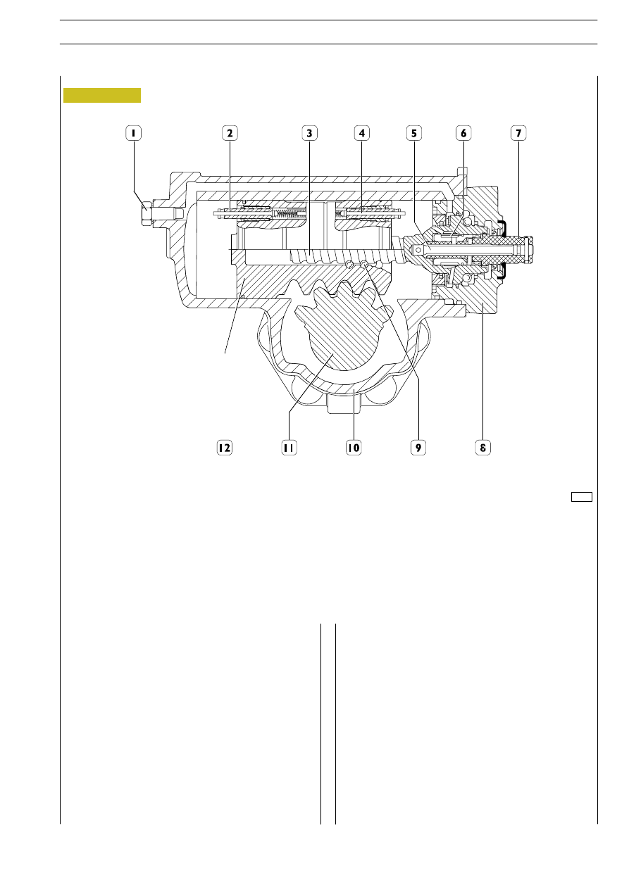
The ball-circulation control hydraulic power steering is
essentially composed of a case in which manual steering
mechanism, an hydraulic cylinder controlled by a rotating
distributor valve, and hydraulic steering and safety limiting
valves are housed.
The rotary motion impressed to steering wheel is transmitted
from inlet shaft (7) to worm screw (3), through the torsion bar
(5).
The worm screw (3) in turn, being connected by means of a
set of balls (9) to the rack piston (12), transforms the rotary
motion into an axial motion of this latter one.
The piston rack toothing (12) meshes into the toothed-sector
shaft toothing and impresses a rotary motion thereto. The
steering control arm fixed on this shaft transmits the motion
to the wheel steering tie-rods.
This only-mechanical steering movement is servoassisted by
the pressurised oil supplied to an engine-actuated blade pump.
If when steering the wheels are subjected to violent impacts,
the force created by the same ones is transmitted through
outlet shaft (11) to rack piston (12) and from it to worm screw
(3). The internal hydraulic power steering system makes the
rotary distributor valve (6) send highly pressurised oil into the
cylinder chamber where such pressure can fight and absorb
the given impact force. In this way no recoils are generated on
the steering wheel.
The hydraulic power steering is equipped with an automatic
air drain valve.
1. Hydraulic steering limiting adjustment screw — 2. Hydraulic right steering limiting adjustment screw — 3. Worm screw —
4. Hydraulic left steering limiting adjustment screw — 5. Torsion bar — 6. Rotating distributor valve — 7. Entry shaft — 8. Cover —
9. Balls — 10. Hydraulic power steering case — 11. Outlet shaft — 12. Rack piston.
Figure 18
E
URO
C
ARGO
T
ECTOR
12-26 t
STEERING
17
Base - February 2003