Iveco EuroCargo (12 to 26 t). Manual - part 154
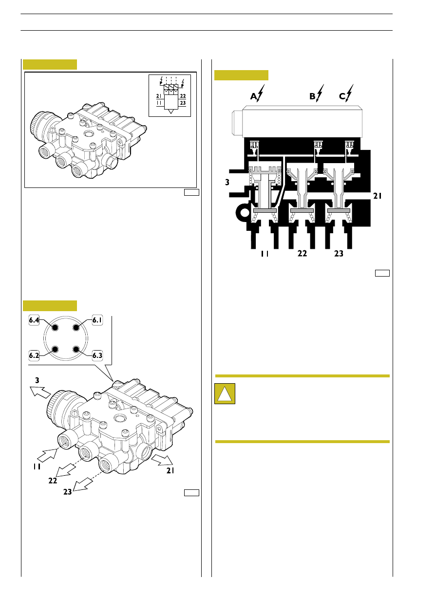
This components consists of three control solenoid valves
”A”, ”B”, ”C” and three pneumatic distributors.
Solenoid valve ”A” manages the supply/discharge distributor.
Solenoid valve ”B” manages the right-hand chassis trim
distributor.
Solenoid valve ”C” manages the left-hand chassis trim
distributor.
The distributor is connected to the system by means of a
four-pole connector.
78805
Figure 22
70117
Figure 23
78806
Operation
Rear axle lowering
In this case, the ECU energises solenoid valves ”B” and ”C”
supplying the second and third distributor, allowing the air to
be relieved from the air springs from duct (3), which is open
because the axle electro-pneumatic solenoid valve ”A” is
de-energised.
Self-leveling
The ECU, according to the position of the level sensors,
controls solenoid valves ”A”, ”B” and/or ”C” accordingly for
lifting or lowering in order to reach vehicle levelling or stored
positions ”M1” or ”M2”.
Pneumatic connections
11 - from air reservoir
21 - to axle electro-pneumatic distributor
22 - to air spring on right-hand side
23 - to air spring on left-hand side
Electrical connections
6.1 - Solenoid valve ”A” power positive
6.2 - Solenoid valve ”B” power positive
6.3 - Solenoid valve ”C” power positive
6.4 - Common negative
Figure 24
!
4x2 P vehicles
Duct (21) is capped.
4x2 FP vehicles
Duct
(21)
is
connected
to
front
axle
electro-pneumatic
distributor
duct
(14)
for
supplying the air springs.
Rear axle lifting
The ECU energises solenoid valve ”A” supplying the first
distributor that closes the relief to atmosphere (3) and opens
the air intake (11) from the reservoir.
The ECU then energises solenoid valve ”B” and ”C” for
supply the second and third distributor and to consequently
supply the rear axle air springs via ducts (22 and 23).
E
URO
C
ARGO
T
ECTOR
12-26 t
68
FRONT AND REAR PNEUMATIC SUSPENSIONS
Base - February 2003