Iveco EuroCargo (12 to 26 t). Manual - part 113
B.
proceed as described in point ”1”;
C. after eliminating the end float further tighten the two
adjustment lock rings (4, Figure 47) to obtain a retraction
of the caps (2) of 0.080 to 0.22 mm, which corresponds
to the sum of the readings on the dial gauges (1).
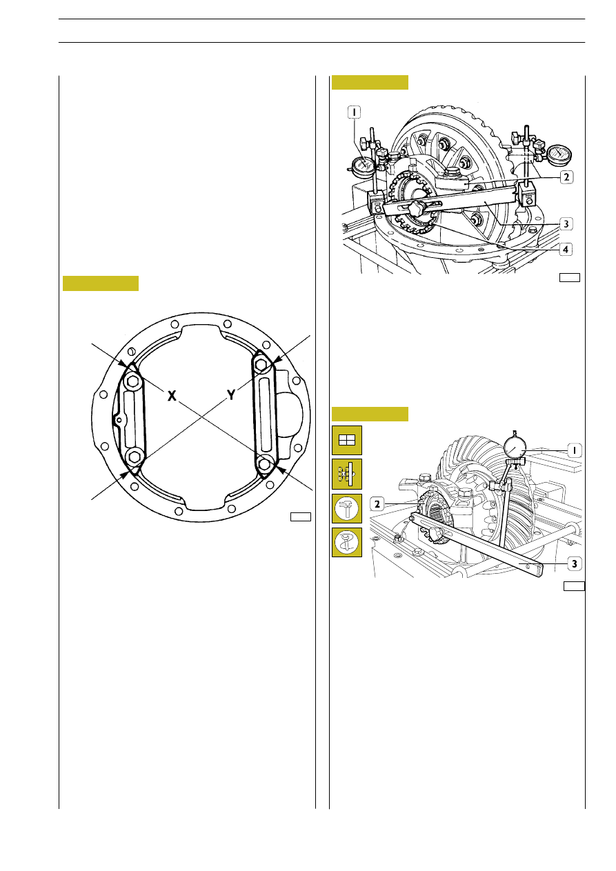
Figure 46
3.
further tighten the two adjustment lock rings (4,
Figure 47) to obtain a retraction of the caps (2,
Figure 47), measured on Axis X or on axis Y as described
in point ”2” of: 0.080 to 0.22 mm which corresponds to
a preload on the bearings of 1.7 to 3.9 Nm (0.17 to 0.39
kgm).
60636
ADJUSTING THE CAP GAP
Adjusting and checking retraction of the caps can be done
with two methods:
1
st
METHOD
1.
Use wrench 99355025 (3, Figure 47) to tighten the
adjustment lock rings (4) of the bearings until eliminating
the pinion-crown wheel clearance and end float. At the
same time check that the crown wheel does not force
on the pinion;
2.
using a suitable micrometer positioned diagonally and
centrally in points (X-Y-arrows, Figure 46);
measure and note the distance of the caps;
2
nd
METHOD
A. Diagonally and centrally on the outer machined seats of
both caps (2, Figure 47) position two dial gauges (1) with
magnetic base as shown in Figure 47;
Figure 47
60635
Adjust the axial clearance between the teeth of the pinion
- crown wheel unit which must be 0.21 to 0.45 mm
proceeding as follows:
- stop the bevel pinion from turning using tool 99370317;
- position the magnetic-based dial gauge (1) as illustrated;
- using wrench 99355025 (3) slacken the adjustment lock
ring on the crown wheel side and tighten, to the same
extent, the adjustment lock ring (2) of the opposite side.
The purpose of this is to leave the previously-adjusted
cap retraction unchanged;
- proceed as described until obtaining the specified
clearance.
The clearance should be checked on 4 points the same
distance apart.
49248
Figure 48
E
URO
C
ARGO
T
ECTOR
12-26 t
AXLES IN TANDEM MERITOR (REAR)
75