Iveco EuroCargo (12 to 26 t). Manual - part 106
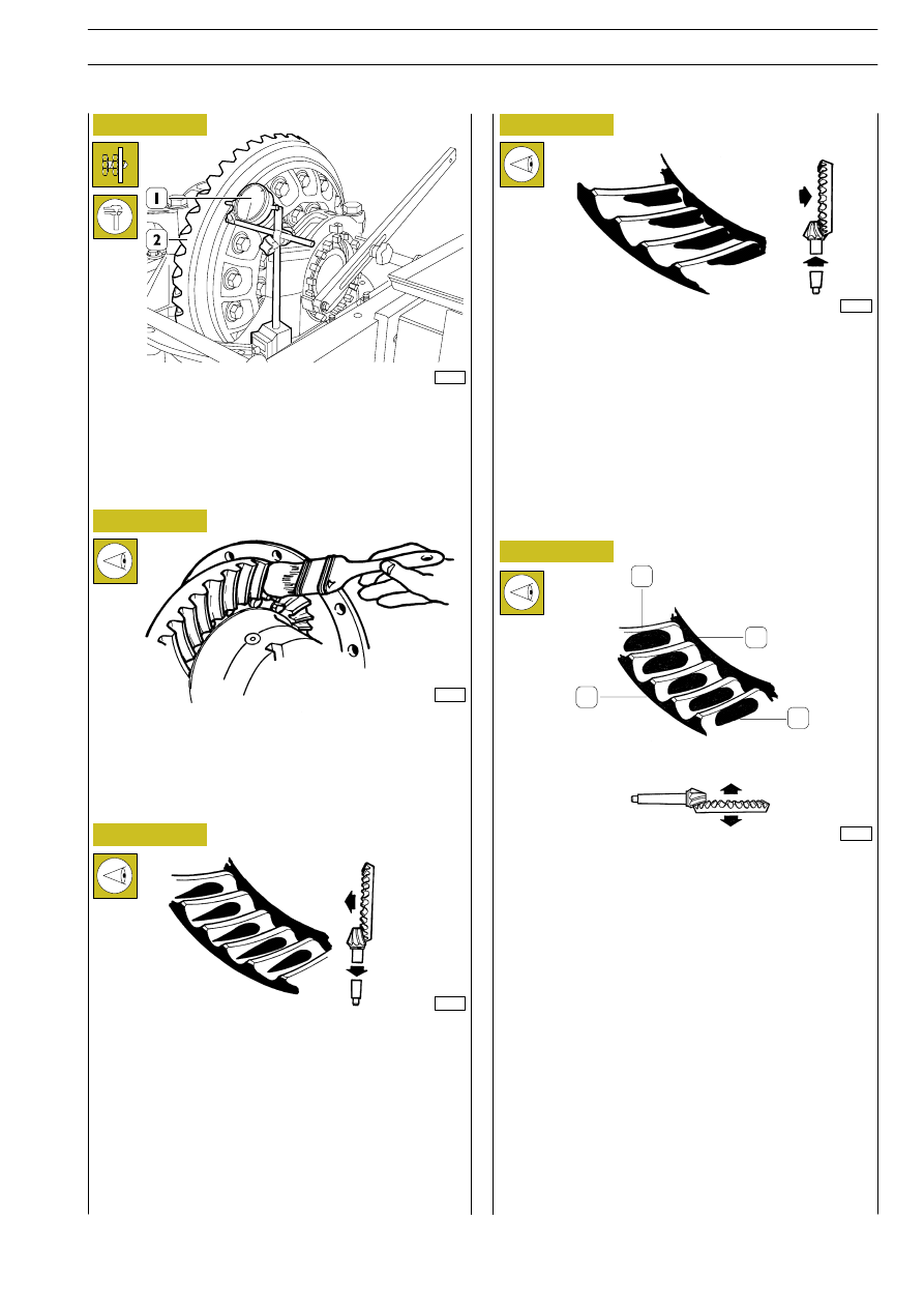
Use a magnetic-based dial gauge (1) to check that the crown
wheel (2) does not have any upper wobble above 0.20 mm.
If it does, disassemble the differential unit and find the cause.
49246
19453
Figure 100
Figure 101
Figure 102
Apply a light layer of Prussian blue on the crown wheel.
Turn the pinion and measure the impression of the contact of
the pinion teeth on the crown wheel teeth.
The following figures show possible contacts and how to
correct any errors.
Refit and repeat the adjustment operations described previ-
ously.
19451
Figure 103
Figure 104
Contacts too much on crown wheel teeth bottom land
Conditions C-D. Indicates that the pinion is fastened too
deeply and needs further adjustment.
To adjust the exact position of the pinion shims should be
added under the pinion support to obtain the exact contact.
Condition C. Measure the clearance and restore it after
adding shims.
Condition D. After adding shims, take the clearance towards
minimum.
19452
Contacts too much towards the crown wheel teeth top land
Conditions A-B. Indicates that the pinion is fastened to much
towards the outside and therefore needs further adjustment.
To adjust the exact position of the pinion, remove shims under
the pinion support to obtain the exact contact.
Condition A. After removing the shims, take the clearance
towards maximum.
Condition B. Measure the clearance and restore it after
removing shims.
19454
Clearance reduction
Clearance increase
1.
Release, concave side of tooth
2.
Top land
3.
Pulling, convex side of tooth
4.
Heel
PULLING. Central tending towards the top land on the tooth
face and central on the tooth profile.
RELEASE. Central tending to the heel on the tooth face and
central on the tooth profile.
Indicates that the pinion is fastened correctly.
The contact position can be further changed by changing the
pinion-crown wheel clearance.
Condition E. Lower the clearance.
Condition F. Increase the clearance.
THEROETICAL CONTACT AREA
1
2
3
4
E
URO
C
ARGO
T
ECTOR
12-26 t
AXLES IN TANDEM (INTERMEDIATE)
45
Base - February 2003