Iveco EuroCargo (12 to 26 t). Manual - part 7
 

  Index      Iveco     Iveco EuroCargo (12 to 26 t) - service repair manual 2003 year


Search            


Content   ..  5  6  7  8   ..


Iveco EuroCargo (12 to 26 t). Manual - part 7


70475

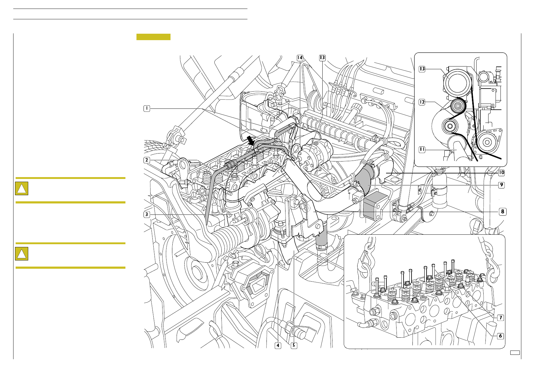
Figure 18

- Remove air-conveyor (9) from turbosupercharger (3)

and intercooler radiator (10);

- Disconnect cooling fluid tubings (1)

For vehicles with air-conditioning:

- Operating on the automatic tightener (11), loosen the

compressor (13) belt tension (12);

- Remove compressor fastening screws (13) to the

support and fix the compressor (13) accurately to avoid
gas tubing damages in the air-conditioning system;

For all types of vehicles:

- Remove heat protection (8);

- Remove exhaust tubing fastening screws (5) and exhaust

brake throttle valve (4) from the turbosupercharger (3),
taking care to fasten the latter to the frame;

- Remove the air tubing bracket fastening screws (2);

- Disconnect oil tubing from the turbosupercharger (3);

- Remove exhaust manifold fastening screws (14) from

the

cylinder

heads

and

remove

it

with

the

turbosupercharger (3).

!

Close the oil and air inlet/outlet holes in the
turbosupercharger to avoid damages caused by
external bodies in it.

!

Place the rocker 99360585 to the cylinder head
lifting bracket. Hook it to the lifter and remove
cylinder heads.

- Remove injectors as described before;

- Remove rocker control rods (6);

- Remove cylinder head fastening screws (7).

E

URO

C

ARGO

T

ECTOR

12-26 t

14

ENGINE

Base - February 2003

Fastening screws closing order chart:

- 1

st

pre-closing step, with dynamometrical wrench:

• Screw 12x1.75x130 ( ) 35

± 5 Nm

• Screw12x1.75 x 150 ( ) 55

± 5 Nm

A= Front side

- 2

nd

90

°±5° angle closing step

- 3

rd

90

°±5° angle closing step

- There are no water drippings from the connecting

manifolds of the engine cooling tubing and the cab
heating, and fasten by blocking collars further if
necessary.

- Low pressure fuel tubing connections and its unions are

correct, as described in “main interventions on an
assembled vehicle”.

- There are no oil drippings between cylinder cover and

head, oil pan and base, heat exchanger oil filter and
lubrication circuit tubings.

- There are no fuel leakages from fuel tubings.

- There are no air losses from pneumatic tubings.

- The warning lights on the instrument panel and the

devices disassembled during the engine removal work
correctly.

Refitting

For refitting invert the operations requested for removal and
follow these warnings:
Check that the cylinder head attack surface and the base are
clean;
Do not dirty the cylinder head gasket;
Assemble cylinder head, fasten and clamp the screws in three
steps, as described in the following figures.

!

Carry out the angle closing with the tool 99395216.

Figure 19

Figure 20

4-cylinder engine

6-cylinder engine

Tests and checks

!

Check that the cooling fluid does not contain filth
before using it; if it does, filter with appropriate net
filters; in case of filling-ups, see the table REFUELING
in the section “GENERAL”.

Start the engine, leave it in motion at a running rate
little more than the minimum and wait that the
cooling fluid temperature reaches the rate for the
thermostat to be opened , then check that:

Assemble injectors as described in the appropriate chapter.

Assemble high and low pressure tubing as described in the
paragraph “main service operations to be performed on
engine fitted on vehicle”.

- Check manifold, cooling fluid and air-conveyor

conditions and replace them in case of damage;

- Fasten the screw to the prescribed torque;

- Fill the cooling system with cooling fluid and bleed as

described before.

70476

70337

A

A

E

URO

C

ARGO

T

ECTOR

12-26 t

ENGINE

15

Base - February 2003

ENGINE F4 AE 0481

70756

E

URO

C

ARGO

T

ECTOR

12-26 t

ENGINE F4 AE 0481

21

Base - February 2003

Type

F4AE0481A

(.17)

Cycle

4 —stroke Diesel

Power Supply

Intercooler supercharged

Injection

Direct

Cylinder number

4 in line

Bore

mm

102

Stroke

mm

120

+

+

+.. =

Total displacement

cm

3

3900

ρ

Compression ratio

17 : 1

Max power

kW
(CV)

rpm

125

(170)

2700

Max. torque

Nm
(kgm)

rpm

560

(57.1)

1200

Idle engine
minimum rpm

rpm

750

Idle engine peak
rpm

rpm

3000


Content   ..  5  6  7  8   ..