Iveco Stralis AT/AD. Manual - part 205
 

  Index      Iveco     Iveco Stralis AT/AD - service repair manual 2003 year


Search            


Content   ..  203  204  205  206   ..


Iveco Stralis AT/AD. Manual - part 205


S

TRALIS

AT/AD

110

STEERING REAR ADDED AXLE 57080/T1 (N 8072)

Base - January 2003

TOOL NO.

DESCRIPTION

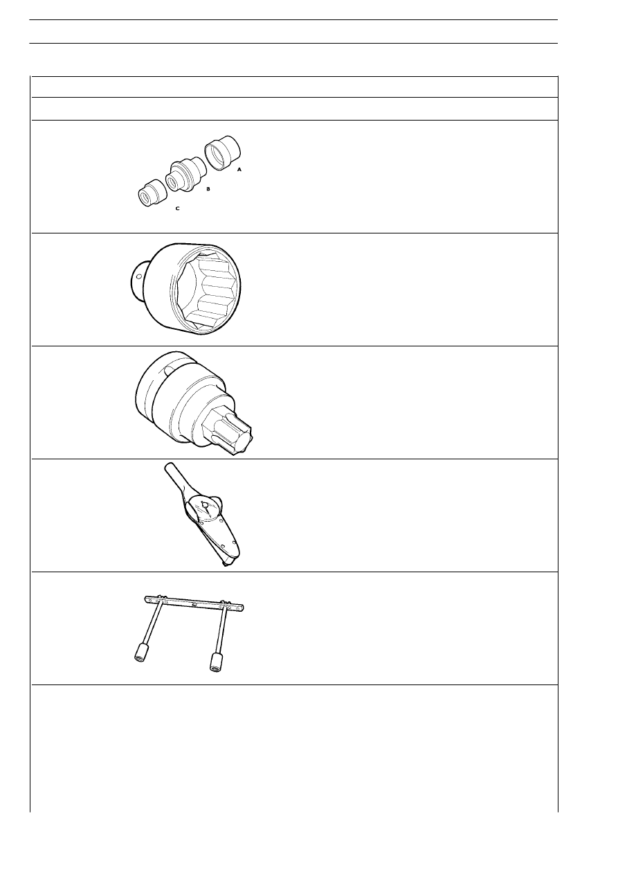
99374530

Drift to remove and refit kingpin bearings (use with 99370007)

99388001

Wrench (80 mm) for wheel hub bearing adjustment ring nut

99388002

Wrench for screws fastening the track rod arm and the drag link
arm to the stub axle

99389819

Torque wrench (0-10 Nm) with 1/4” square fitting

99395026

Tool for testing hubs rolling torque
(to be used with torque wrench)

REPAIR OPERATIONS

For the procedure for overhauling the wheel hubs, follow the directions given under the heading AXLE 55080/TI with drum brakes.

The adjustment data, tightening torques and tools are the ones given in this section.

For a description of operation, characteristics and data and the repair procedures for the hydraulic and pneumatic components,
follow the directions given under the heading axle 57080/DI.

WHEEL GEOMETRY

111

S

TRALIS

AT/AD

Page

GENERAL INFORMATION

113

. . . . . . . . . . . . . . . .

- Steering wheel angles

113

. . . . . . . . . . . . . . . . . . .

FRONT WHEEL GEOMETRY

(4x2 vehicles)

114

. . . . . . . . . . . . . . . . . . . . . . . . .

- Positioning clips and headlights

114

. . . . . . . . . . . .

- Electronic compensation of rim eccentricity

115

. .

- Wheel alignment

115

. . . . . . . . . . . . . . . . . . . . . . .

- Checking wheel toe-in

116

. . . . . . . . . . . . . . . . . .

- Checking wheel deviation

116

. . . . . . . . . . . . . . . .

- Checking camber

116

. . . . . . . . . . . . . . . . . . . . . . .

- Checking kingpin angle and caster

117

. . . . . . . . . .

- Checking rear axle alignment

118

. . . . . . . . . . . . .

VEHICLE WHEEL GEOMETRY WITH CENTRAL

ADDED AXLE (6X2 C)

118

. . . . . . . . . . . . . . . . .

- Checking rear axle alignment

120

. . . . . . . . . . . . .

- Vehicle wheel geometry with steering rear added

axle and pneumatic lifting

120

. . . . . . . . . . . . . . . .

112

WHEEL GEOMETRY

S

TRALIS

AT/AD

Base - January 2003

To ensure satisfactory road holding performance, low tyre wear
and to allow driving wheels in the steering stage to return spon-
taneously to straight ahead running position, front wheels are
given the following fitting angles:

Figure 1

The kingpin angle (ß) is the angle formed by the axis passing
through the kingpin and the vertical to the ground when
observing the vehicle from the front.
When the extension of the kingpin axis approaches the wheel
at its point of contact with the ground (opposite to the camber),
the angle is positive; it is extremely difficult, if not impossible, to
have a negative kingpin angle.
The camber (

α) and kingpin angle (ß) make it possible for the

axes of the wheel and kingpin to come as close as possible to
the centre of support of the tyre on the ground.
This produces low tyre consumption and a low steering torque.

Caster

Camber

The camber (

α) is the angle formed by the axis passing

through the centre line of the wheel and the vertical to the
ground when observing the vehicle from the front.
The angle is positive (A) when the top of the wheel tilts
outwards, negative (B) when the top of the wheel tilts inwards.

32956

32957

32958

Figure 2

A

B

α

α

ß

The caster (

γ) is the angle formed by the kingpin axis with the

vertical to the ground when observing the vehicle from the side.
If the extension of the kingpin axis falls forwards to the point
where the wheel rests on the ground, in the direction of travel
of the vehicle, the caster is by convention positive (A); it is
negative (B) if it falls behind the point where the wheels rest on
the ground, and zero if it is exactly vertical to the point where
the wheels rest on the ground.
This angle makes it possible to keep the front wheels straight
when the vehicle is travelling in a straight line and for them to
return straight on their own after the position they take in a
bend as soon as the driver lets go of the steering wheel.

A

B

+

_

γ

γ

Steering wheel angles

Kingpin angle

These angles, suitably calculated, produce the right balance of
the forces created when the vehicle is moving, in different load
conditions, which tend to alter the position of the wheels on the
ground.

- camber;
- kingpin angle;
- caster;
- toe-in.

Figure 3

WHEEL GEOMETRY

113

S

TRALIS

AT/AD

r

GENERAL INFORMATION


Content   ..  203  204  205  206   ..