Iveco Daily. Manual - part 436


  Index      Iveco     Iveco Daily - service repair manual 2004 year


Search            


Content   ..  434  435  436  437   ..


Iveco Daily. Manual - part 436


270

ELECTRIC/ELECTRONIC SYSTEM

D

AILY

Base - May 2004

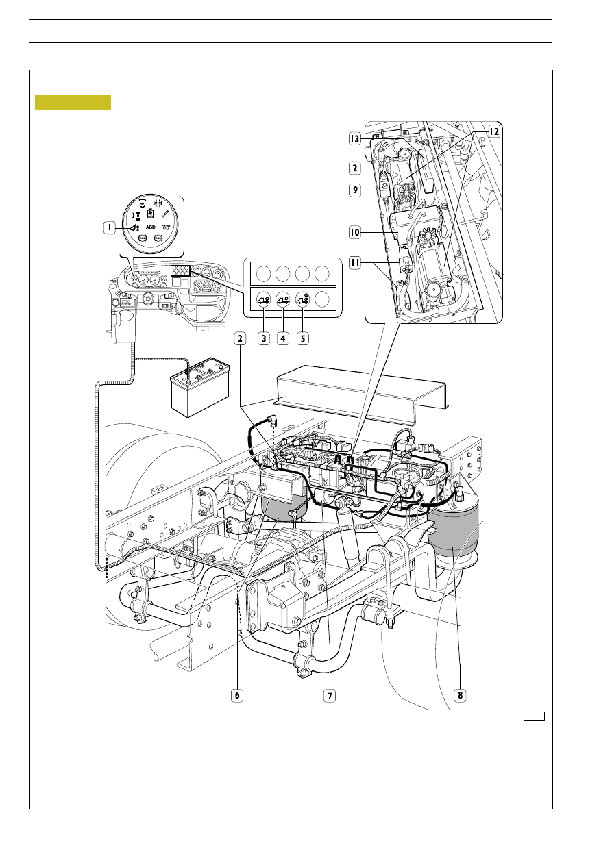
1. VBT waring lamp - 2. Suspension control unit (ECU, pneumatic supply unit) - 3. Chassis lifting switch - 4. Chassis lowering

push-button - 5. Manual control button - 6. RH air spring - 7. Level sensor -  8. LH air spring

Figure 314

85724

ELECTRIC/ELECTRONIC SYSTEM

271

D

AILY

SYSTEM COMPONENTS
Electronic Control Unit (35C - 40C - 45C)

The electronic control unit controls different chassis positions in accordance with the driver's requests.
As the ignition key switch is turned to ON position, the electronic central unit runs a system check while the red warning lamp

on the dashboard panel comes on for about 5 seconds.
If no failures are detected, this warning lamp shall turn off, otherwise an automatic blink code shall be started with the following

meaning:
Slow blinking

-

Electric compressor overload due to prolonged manual actuation.

Fast blinking

-

Electric compressor overload

Fixed on

-

Level sensor cable

Off

-

Supply failure

Dimmed light

-

Wrong button operation (simultaneous action) or button connecting cabling failure.

The control unit is fitted with a warning led 1" connected to the warning lamp on the dashboard panel,  and a set of five

connectors  2" of which only  1, 3 and 5 are used.

Connector

Pin

Function

Cable colour

1

Signal from level sensor

White

2

Signal from level sensor

Brown

1

3

Positive from level sensor

Yellow

1

4

Negative from level sensor

Green

5

-

-

6

-

-

1

Signal from lifting switch

Grey

2

Negative for trim variators

Green

3

3

Signal from lowering switch

Brown

3

4

Negative for failure warning light

Yellow

5

Key-controlled positive

Pink

6

Signal from handbrake switch

White

1

Electric compressor control remote-control switch positive

White

2

Discharge solenoid valve control positive

Yellow

5

3

Positive from battery

Red

5

4

Negative from battery

Black

5

-

-

6

-

-

Figure 315

000373t

272

ELECTRIC/ELECTRONIC SYSTEM

D

AILY

Base - May 2004

Pin

Cable colour

Function

1

Pink

+15

2

Yellow

Warning light bulb

3

Green

Button negative

4

White

Signal from handbrake

5

Brown

Lowering button

6

Grey

Lifting button

7

-

Free

8

-

Free

9

-

Free

10

-

Free

11

-

Free

12

Black

Tachograph

13

White

Signal from level sensor for lifting

14

Brown

Signal from level sensor for lowering

15

Yellow

Positive for level sensor

16

Green

Negative for level sensor

17

Green

Earth

18

Pink

+30

19

Brown

Discharge solenoid valve control

20

Grey

Compressor relay 2 control

21

Yellow

Discharge solenoid valve control

22

White

Compressor relay 2 control

Figure 316

004283t

ELECTRIC/ELECTRONIC SYSTEM

273

D

AILY

Level sensor

In accordance to the chassis height from floor, the level sensor

shown sends the signals to start chassis leveling to the ECU.
It is connected to the control unit by means of four cables:

- White:

Lifting signal

- Brown:

Lowering signal

- Yellow:

Positive

- Green:

Negative

Pneumatic supply unit
The  function  of  this  component    is  that  of  distributing  or

discharging suspension spring air.

Shows  the  connection  of  its  internal  components  of  the

supply unit..
Components of the pneumatic supply unit
1 - Air spring relief solenoid valve 

2 - Dryer filter

3 - Compressor

4 - Supply filter

5 - Electrical motor

6 - Relief pneumatic valve

7 - Muffler

LEVEL SENSOR

PNEUMATIC SUPPLY UNIT

Figure 317

Figure 318

000374t

000375t


Content   ..  434  435  436  437   ..