Iveco Daily. Manual - part 329
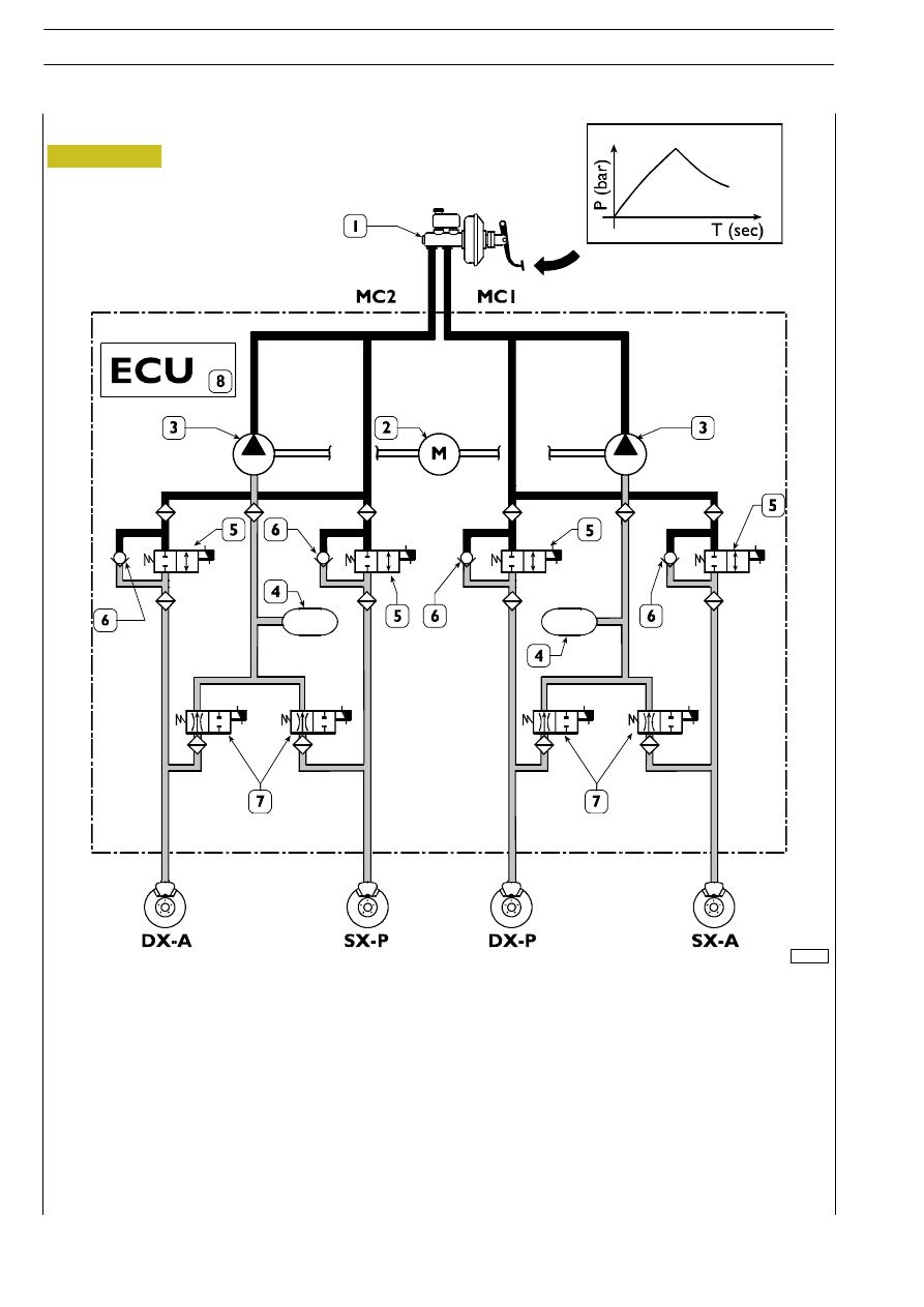
Pressure decrease
1. Vacuum servobrake - 2. Scavenge pump control motor - 3. Scavenge pumps - 4. Low pressure accumulators -
5. Power supply solenoid valves - 6. Quick pressure decrease single-acting valves - 7. Discharge solenoid valves -
8. Electronic control unit - DX/A. Front axle right wheel sensor - SX/A. Front axle left wheel sensor -
DX/P. Rear axle right wheel sensor - SX/P. Rear axle left wheel sensor
If the sensors find that the wheel(s) tends to get locked, they will inform the control unit: the latter will reduce the braking power
by actuating power supply solenoid valves “5” and discharge solenoid valves “7”.
At the same time, the excess oil in low pressure accumulators can be recovered by powering motor “2” which drives pumps “3”.
102268
Figura 46/1
51/5
HYDRO-PNEUMATIC SYSTEM - BRAKES
D
AILY
Revi - February 2005