Iveco Daily. Manual - part 111
F1A ENGINE
D
AILY
422
Base - May 2004
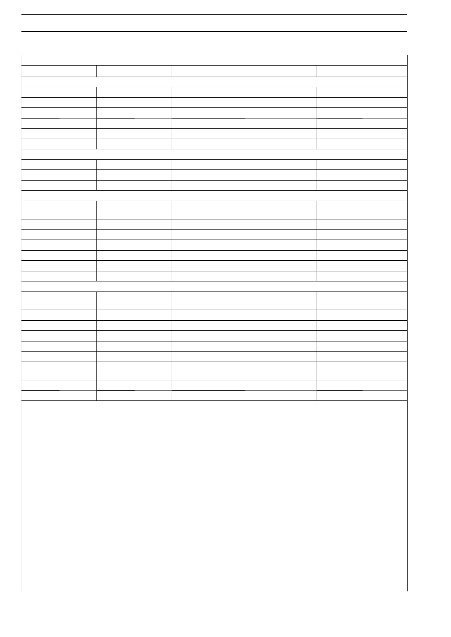
Blink code
Indicator light
Fault description
Power reduction
ELECTRO-INJECTORS
5.1
Blinking
Cylinder 1 injector solenoid valve
5.2
Blinking
Cylinder 2 injector solenoid valve
5.3
Blinking
Cylinder 3 injector solenoid valve
5.4
Blinking
Cylinder 4 injector solenoid valve
5.7
Blinking
Bank 1 (cylinders 1 — 4)
5.8
Blinking
Bank 2 (cylinders 2 — 3)
ENGINE SPEED
6.1
Blinking
Crankshaft sensor
*
6.2
Blinking
Timing sensor
*
6.4
Off
Engine overspeed
FUEL PRESSURE
8.1
Blinking
Fuel pressure control
*
or cutting out engine
8.2
Blinking
Fuel pressure sensor
*
8.3
Blinking
Pressure regulator solenoid valve
8.5
On
EGR monitoring
8.6
On
EGR solenoid valve
8.7
On
Debimeter
8.8
Off
Air temperature sensor (debimeter)
CONTROL UNIT
9.1
Blinking
Control unit error (Gate array)
*
or cutting out engine
9.2
On
Control unit error (EEPROM)
9.3
Blinking
EDC — Immobilizer communication
9.4
On
Main contactor
9.5
Off
After run test
9.6
Blinking
Engine Stop Test (ECU)
9.7
Blinking
Sensor power supply
*
or cutting out engine
9.8
Blinking
Control unit error (Checksum)
Starting not possible
9.9
Blinking
Control unit error (Operating system)
Cutting out engine
(
∗) Cases when there is a power reduction.