Iveco Daily. Manual - part 90
75816
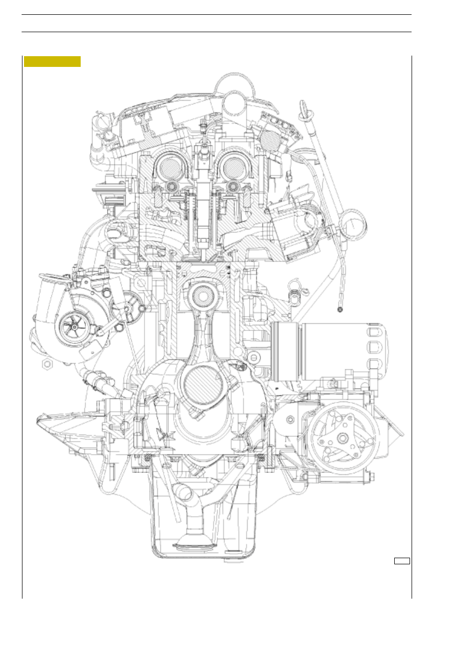
Figure 24
TRANSVERSE CROSS-SECTION OF ENGINE WITH E.G.R.
F1A ENGINE
D
AILY
338
Base - May 2004
|
|
|
75816 Figure 24 TRANSVERSE CROSS-SECTION OF ENGINE WITH E.G.R. F1A ENGINE D AILY 338 Base - May 2004 |