Iveco Daily Euro 4. Manual - part 195


  Index      Iveco     Iveco Daily Euro 4 - service repair manual 2006 year


Search            


Content   ..  193  194  195  196   ..


Iveco Daily Euro 4. Manual - part 195


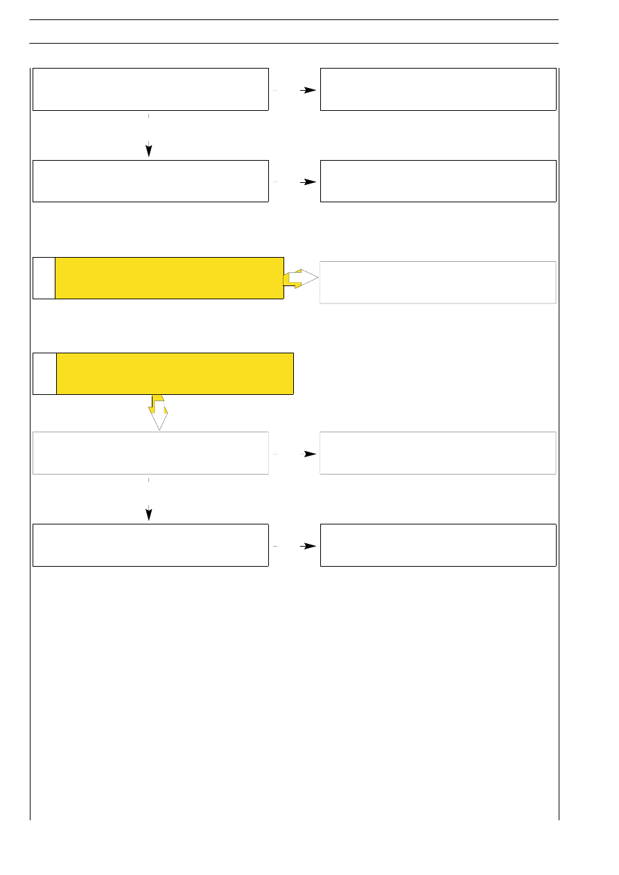
Oil leaking from couplings in power steering
circuit

YES

NO

YES

Check coupling seals for serviceability, replacing any
which are worn

Insufficient oil level in the tank

Top up level and bleed circuit

9

THE VEHICLE TENDS TO

MOVE SIDEWARDS

Replace the power steering unit

Check the windings and in case replace oil pressure
sender.

Oil pressure sender malfunction

10

YES

NO

HYDRAULIC POWER STEERING PILOT

LIGHT ALWAYS LIGHTED

YES

Hydraulic power steering oil level low

Top up oil

10

STEERING GEAR

D

AILY

E

URO

4

The distributor consists of:
- a drive shaft (1) (joined to the steering column);

- a distributing valve (4);

- a wrench bar (3);

- a pinion (6).
The drive shaft is elastically joined by the wrench bar to the
pinion by means of the pin (2). The distributing valve, trigged
on the drive shaft is integral with the pinion by means of a pin
(5); it has holes and splines in order to receive and distribute
the oil flow to the hydraulic cylinder. Besides, a stiff joint (A)
ensures the mechanical working of the hydraulic power
steering in case of failure of the hydraulic system, through a
bayonet joint.

24103

Figure 2

The power steering system consists of:
- a tank (A);

- a blade pump (B) with delivery regulating valves (C);

- a series of connecting pipings (D);

- an hydraulic power steering (E).
The oil tank, in the engine compartment, feeds the blade pump.
This pump is able to provide a feeding pressure ranging from
a minimum of approx. 4 bar to a maximum of approx. 80+10.
The oil come to the steering box, which is similar to a
mechanical steering as for general building features, from the
pump.
In fact, its operation is mechanical for pinion to rack coupling,
The rack rod is joined to the wheels with two side tie rods.
The system is self-bleeding; bleeding is performed by
completely steering to the right or to the left with the engine
started and the vehicle stopped.
The oil level check must be performed with the engine started.

24104

Figure 3

The hydraulic part of the steering box consist of:

- a distributor (3);

- an hydraulic cylinder (1);

- a double-acting piston (4) integral with the rack rod.

The hydraulic connection between distributor and hydraulic
cylinder is achieved using two stiff pipes (2). The distributor (3)
is integral with the hydraulic power steering pinion.

HYDRAULIC POWER STEERING SYSTEM DIAGRAM

HIGH PRESSURE

LOW PRESSURE

A

6

1

3

2

4

5

1

2

3

4

E

The description below concerns the TRW hydraulic
power steering and due to their similarity, it also
applies to the ZF hydraulic power steering.

NOTE

STEERING GEAR

11

D

AILY

E

URO

POWER STEERING
Description

HYDRAULIC POWER STEERING OPERATION DIAGRAM: NEUTRAL POSITION

The hydraulic cylinder (1) is integral part of the hydraulic power steering, The double-acting piston (2) (integral with the rack rod)
slides in the hydraulic cylinder and divides it into two separate chambers A and B.
The power steering is obtained by sending oil under pressure into one of the hydraulic cylinder chambers and discharging it into the
other one. The power generated by the oil pressure on the side surface of the piston causes the movement of the piston and, as
a result, of the rack. The feeding of one of the two hydraulic cylinder chambers occurs when the torque applied to the steering wheel
causes the wrench of the bar; in this condition, the port of the drive shaft and the relevant ports of the distributing valve are joined
depending on the rotary direction of the steering wheel. If the amount of torque applied to the steering wheel does not cause the
wrench of the bar (low wheel resistance), the power steering does not intervene and the steering operates as a mechanical one.

24105

24106

Figure 4

Figure 5

The oil coming from the pump through the joint (3) goes into the distributing valve, circulates in it and returns in the tank through
the joint (4), simultaneously passing through the chambers (2) and (1).
The drive shaft (A), since it is not subject to wrench, is centred with respect to the distributing valve (B) and drives the oil coming
from the pump directly into the tank through the ports (C). The chokes caused by the shaft (A) position with respect to the
distributing valve (B) cause a pressure of ~ 3.5 bar in the right and left chamber through the ports (D) and (E).

HIGH PRESSURE

LOW PRESSURE

12

STEERING GEAR

D

AILY

E

URO

4

HYDRAULIC POWER STEERING OPERATION DIAGRAM: RIGHT STEERING

24108

Figure 6

The oil coming from the pump through the joint (3) goes into the distributing valve and it is sent to the hydraulic cylinder chamber
(1) causing the movement of the piston.

This movement pushes the oil contained into the chamber (2), through the joint (4), into the tank, passing again in the distributing
valve. The movement of the piston in the direction of the arrow shows a right steering.

The drive shaft (A), rotating clockwise with respect to the distributing valve (B), drives the oil under pressure coming from the pump
through the ports (C), to the left chamber along the ports (E) and joins the discharge and the right chamber circuit by means of the
ports (D).

HIGH PRESSURE

LOW PRESSURE

STEERING GEAR

13

D

AILY

E

URO


Content   ..  193  194  195  196   ..