Iveco Daily Euro 4. Manual - part 63
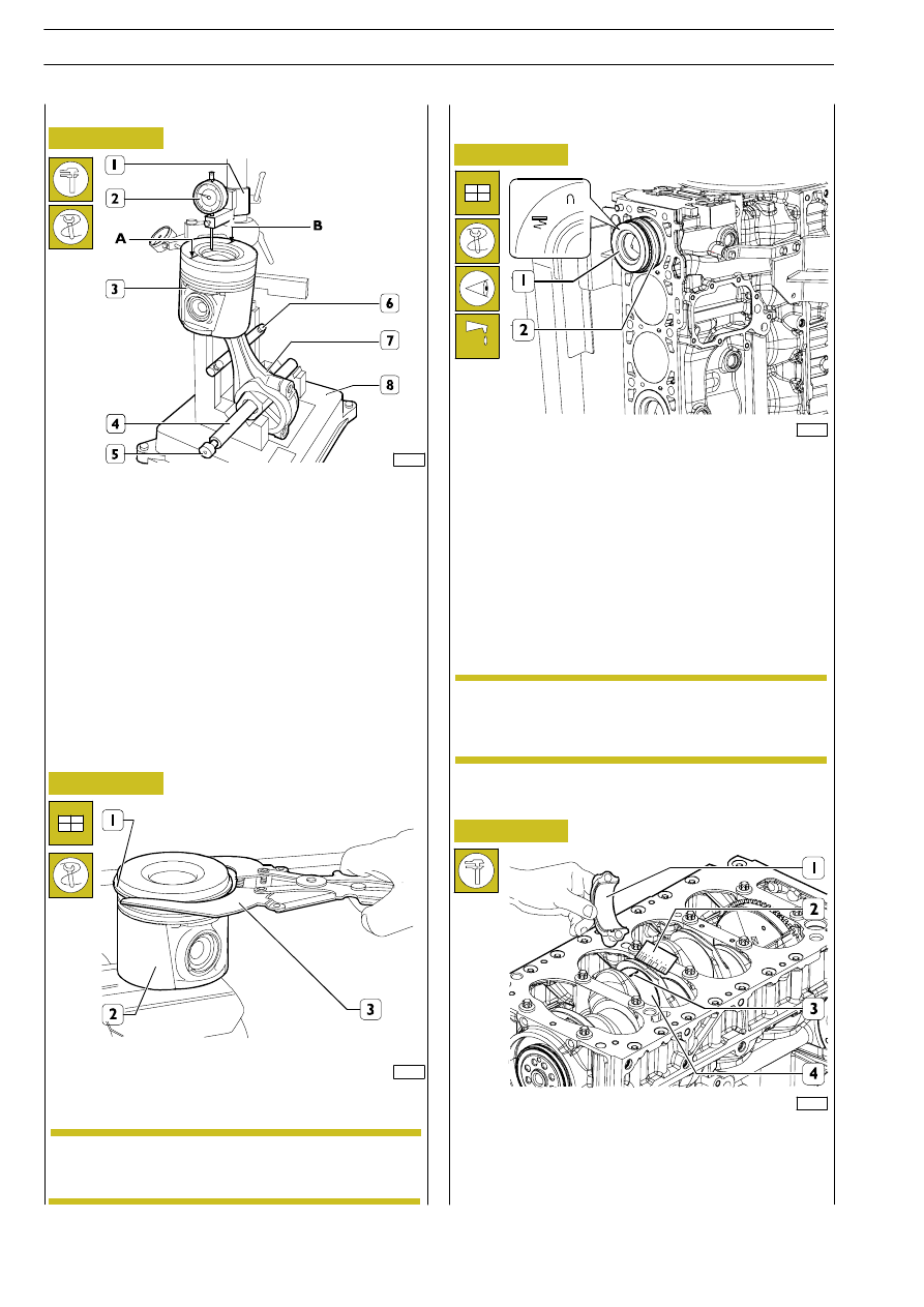
Figure 168
Figure 169
Figure 170
Figure 171
Checking for connecting rod — piston distortion
Assembly piston rings
Fit the piston rings (1) on the piston (2) using the pliers
99360183 (3).
Assembly connection rod-piston assembly in
the cylinder liner
88302
Lubricate the pistons well, including the piston rings and the
inside of the cylinder liners.
With the aid of the clamp 99360605 (2), fit the connecting
rod — piston assembly (1) in the cylinder liners, checking that:
- The number of each connecting rod corresponds to the
cap mating number.
- The openings of the piston rings are staggered 120
° apart.
- The pistons are all of the same weight.
- The symbol punched on the top of the pistons faces the
engine flywheel, or the recess in the skirt of the pistons
tallies with the oil spray nozzles.
After fitting the connecting rod — piston assembly together,
check for distortion with the tool 99395363 (8) as follows:
- Fit the connecting rod (7) together with the piston (3)
on the spindle (4) of tool 99395363 (8) and lock it with
the screw (5).
- Rest the connecting rod (7) on the bar (6).
- Position the mount (1) of the dial gauge (2) so that this
is positioned at point A of the piston with a pre-load of
0.5 mm and zero the dial gauge (2).
- Shift the spindle (4) so as to position the dial gauge (2)
at point B of the piston (3) and check for any deviation.
75403
41097
540831
Measuring crankpin assembly
clearance
88303
To measure the clearance, carry out the following steps:
- Thoroughly clean parts (1) and (4) and eliminate all
traces of oil.
- Place a length of calibrated wire (3) on the crankshaft
pins (4).
The 1
st
and 2
nd
slot rings need to be mounted with
the word ”TOP” facing upwards.
NOTE
Not finding it necessary to replace the connecting
rod bearings, you need to fit them back in exactly
the same sequence and position found on
disassembly.
NOTE
244
F1C ENGINE
D
AILY
E
URO
4