Engine Iveco Vector 8. Manual - part 29
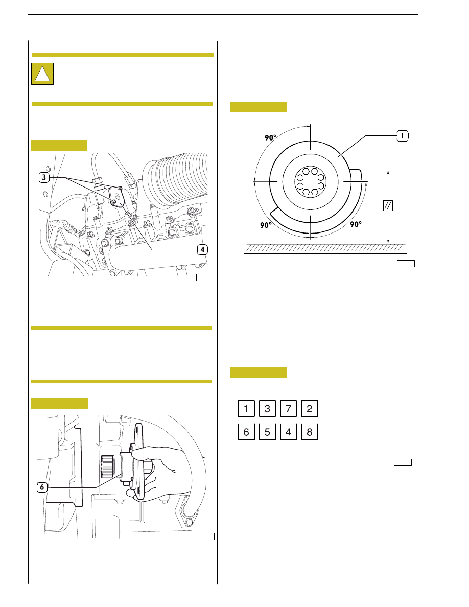
Figure 6
Figure 7
Figure 8
Figure 9
- Unscrewing the relevant screws (3), remove the 16
covers of the tappet housings (4).
- Fit the tool 99368502 (6) in correspondence with the
inside of the flywheel housing (opposite side to the
starter motor).
!
Handle all parts extremely carefully. Never get
your hands or fingers between pieces. Wear the
required safety clothing such as goggles, gloves,
safety shoes and helmet.
To adjust the rocker arm assembly, proceed as illustrated
here:
In maintenance conditions with the engine on the
stand to obtain greater precision in positioning
cylinder 1 at T.D.C. it is also possible to remove the
tappet cover.
- Fitting the 24 mm ratchet wrench on the back of tool
99368502 (see preceding page), turn the engine flywheel
until we obtain the required cylinder balancing (the 4
valves are at the same height).
- To obtain cylinder no.1 or no.6 in T.D.C. conditions it is
necessary to position the damping flywheel as indicated
in the picture.
For
the
following
balancing/adjustments
it
is
recommended to trace some marks on the elastic joint
drive wheel, placed at 90
° one from theother.
- After obtaining this condition of balancing we move on
to adjust the valves in the following order.
BALANCING
ADJUST
FIRST STEP
83505
81601
ADJUSTING ROCKER ARM ASSEMBLY
NOTE
81605
81603
88
SECTION 3 - INDUSTRIAL APPLICATION
VECTOR 8 ENGINES
Base - April 2006
Print P2D32V001E